CET supply air VAV box, pressure sensor, duct area, venturi valve (CetVavSu15)
SOverview
The application function "CET room pressurization supply air VAV box 15, differential pressure sensor, duct area, internal air flow controller, venturi valve" (CetVavSu15) operates a venturi air valve, using both closed loop and open loop control to drive the measured flow to an airflow setpoint (VavSuSpAirFl) that it calculates based on demand signals received for heating, cooling and ventilation. It can control airflow with a settling time of 1 to 2 seconds when applied with the right peripheral devices. It can also be set up for slower operation.
The main output is a modulating output for venturi air valve position (VavSuPos) that is generated by a PID airflow controller in this AF. Functions to support air balancing and venturi air valve calibration are included.
Note
To calculate supply air volume flow, this AF uses a duct areacalculation and input from a differential pressure sensor.
Main features:
- VAV supply air valve modulation for temperature control and ventilation purposes
- Venturi Air Valve calibration and characterization
- Airflow setpoint calculation
- Airflow calculation
- Airflow coefficient calculation (air balancing logic)
- Interlocks (box coils)
- Supply chain interface
- Pressurization
Function
The figure below shows BACnet objects associated with this application function. Primary signal flow is summarized as follows:
Basic function: Accept request signal(s) (VavSuSpAflRel and VavSuAflScale) from associated room controller and map it to appropriate airflow setpoint; Pass result through a device mode logic switch prior to outputting as a command to the air flow setpoint object (VavSuSpAirFl); Compare setpoint to airflow in terminal box.
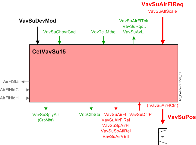
| Command or request (or related) |
| Notification of condition or status, or availability |
| Device mode |
| Interlock (internal signal, not a BACnet object; see Interlocks section for additional information) |


Device mode: The input signal for device mode is a multistate value.
VavSuDevMod supports the following states:
- Off
- Control mode
- Max.air vol.flow
- Min.air vol.flow
- Smoke ctrl.air flow setp.
Available status: When the VAV supply damper is available for heating or cooling or ventilation, the respective binary output signal(s) that indicate availability (VavSuAvlH, VavSuAvlC, VavSuAvlVnt) will be "Yes" (available).
For available status to be "Yes", device mode must equal "Control mode" (modulation) and VavSuChovrCnd (Supply air VAV changeover condition) cannot equal "Neither".
Airflow control loop (cascade control)
Airflow controller: The PID airflow controller (VavSuAirFlCtr) compares the airflow volume of the Venturi valve to the current VAV supply airflow setpoint, and modulates VavSuPos as necessary to keep the box flow at setpoint.
ABT 5.x and later:
Airflow setpoint selection: The AF calculates the airflow setpoint for the terminal to satisfy the demand of one of the supported airflow drivers:
- Heating
- Cooling
- Ventilation
- Make-up
The AF maps the demand level in percent to the flow range (min/max values) configured for the active driver. The result is the airflow setpoint for the terminal in physical flow units (ft3/min, m3/h, l/s). Mapping of the demand level to the flow range is as shown in the diagram.
The objects indicating demand level, (VavSuAirFlReq) and the active driver (VavSuAflScale) are inputs to the AF. They are written by other functions. The airflow limits for the terminal are configured here.
|
|
Cooling | Heating |
|
|
Ventilation | Make-up |
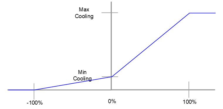
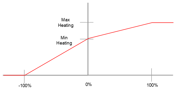
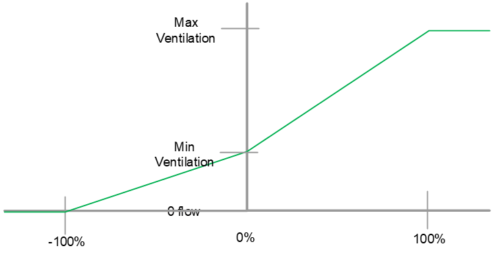
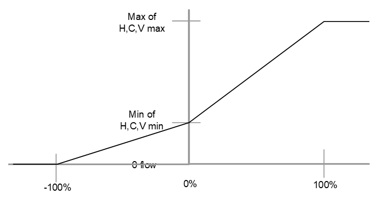
That setpoint mapping is normal operation. It applies when the device mode (VavSuDevMod) is Control Mode. Special values of device mode alter the setpoint as follows:
- Off – Setpoint is 0 and damper is closed
- Control Mode – Setpoint follows % demand
- Maximum airflow setpoint – Setpoint is maximum for the currently active airflow scale
- Minimum airflow setpoint – Setpoint is minimum for the currently active airflow scale
- Manual airflow setpoint – Setpoint is value configured for smoke control
Supply Air Flow Limits for Air Terminals - Configuration
The Supply Air Flow serves multiple functions: heating, cooling, ventilation, and pressurization. The following section explains how to configure each supply terminal for different use cases.
Cooling | Heating | Ventilation | |
Single CV (Constant Volume) Supply Terminal | Min = Max = 0 (or minimum flow value needed for the coil to cool the room) | Min = Max = 0 (or minimum flow value needed for the coil to heat the room) | Min = 0 |
Single VAV (Variable Air Volume) Supply Terminal (no fume hood) | Min = 0 (or minimum flow value needed for the coil to cool the room) | Min = 0 (or minimum flow value needed for the coil to heat the room) | Min = 0 |
Single VAV Supply Terminal (fume hood) | Min = 0 (or minimum flow value needed for the coil to cool the room) | Min = 0 (or minimum flow value needed for the coil to heat the room) | Min Ventilation = 0 |
Check the project specification to see if the various terminals are to be sequenced differently from each other: if they respond to different needs. If no difference is specified, follow the next table's instruction. If the flow limits are set the same for each terminal, then they run at equal flows.
Cooling | Heating | Ventilation | |
Multiple Supply Terminals (same size, same function) | Min = 0 (or minimum flow value needed for the coil to cool the room) | Min = 0 (or minimum flow value needed for the coil to heat the room) | Min = 0 |
Check the project specification to see if the various terminals are to be sequenced differently from each other: if they respond to different needs. If the supply terminals are different sizes but have the same function, follow the next table's instruction.
Cooling | Heating | Ventilation | |
Multiple Supply Terminals (different sizes, same function) | Min = 0 (or minimum flow value needed for the coil to cool the room) | Min = 0 (or minimum flow value needed for the coil to heat the room) | Min = 0 |
In the case of multiple supply terminals with different functions, the following tables provide an example of how to configure one CV (Constant Volume) Terminal serving a chilled beam, and one VAV (Variable Air Volume) Terminal without cooling.
Flow through the CV Terminal does not vary to heat or cool.
Flow is always set by ventilation or support for coil (minimum heat or minimum cooling) unless reducing it is the only way to maintain room pressurization.
Flow through the VAV Terminal may vary for heating, cooling, and ventilation, or to balance fume hood flow.
Cooling | Heating | Ventilation | |
Multiple Supply Terminals (different functions) | Min = Max = 0 (or minimum flow value needed for the coil to cool the room) | Min = Max = 0 (or minimum flow value needed for the coil to heat the room) | Min = Max = 0 (or value needed to support a heating or cooling coil) |
Multiple Supply Terminals (different function) | Min = 0 (or minimum flow value needed for the coil to cool the room) | Min = 0 (or minimum flow value needed for the coil to heat the room) | Min = 0 |
ABT 4.x and earlier
Airflow setpoint selection: The AF calculates the airflow setpoint for the terminal to satisfy the demand of one of the supported airflow drivers:
- Heating
- Cooling
- Ventilation
- Make-up
The AF maps the demand level in percent to the flow range (min/max values) configured for the active driver. The result is the airflow setpoint for the terminal in physical flow units (ft3/min, m3/h, l/s). Mapping of the demand level to the flow range is as shown in the diagram.
|
|
Cooling | Heating |
|
|
Ventilation | Make-up |
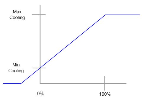
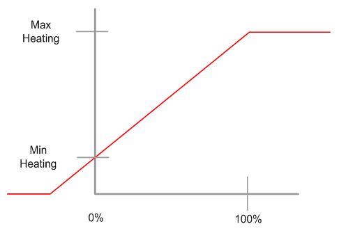
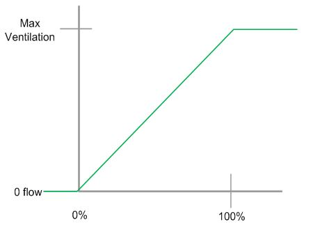
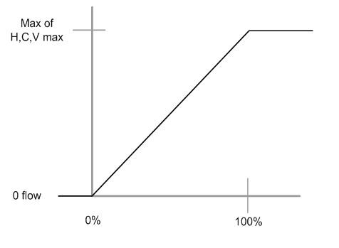
The objects indicating demand level, (VavSuAirFlReq) and the active driver (VavSuAflScale) are inputs to the AF. They are written by other functions. The airflow limits for the terminal are configured here.
That setpoint mapping is normal operation. It applies when the device mode (VavSuDevMod) is Control Mode. Special values of device mode alter the setpoint as follows:
- Off – Setpoint is 0 and damper is closed
- Control Mode – Setpoint follows % demand
- Maximum airflow setpoint – Setpoint is maximum for the currently active airflow scale
- Minimum airflow setpoint – Setpoint is minimum for the currently active airflow scale
- Manual airflow setpoint – Setpoint is value configured for smoke control
Airflow control with Venturi air valve: The AF has three ways to control airflow with the Venturi valve: PID control, a linear characterization curve, and the linear characterization curve combined with PID control. The user selects the loop control by setting the configuration property (AirFlCtlMod) and by setting up the data table for the characterization curve.
AirFlCtlMod | Characterization Curve | Setpoint | Control action |
|---|---|---|---|
closed loop | configured | > AirVMinCtlClb | combined |
closed loop | configured | < AirVMinCltClb | curve only |
closed loop | not configured | any | PID only |
closed loop | configured | any | curve only |
closed loop | not configured | any | fail mode |
open loop | configured | > AirVMinCtlClb | curve only |
open loop | configured | < AirVMinCltClb | curve only |
open loop | not configured | > AirVMinCtlClb | curve only (output to actuator will be zero) |
open loop | not configured | < AirVMinCltClb | curve only (output to actuator will be zero) |
open loop | configured | any | curve only |
open loop | not configured | any | fail mode |
-- | calibrating | -- | curve |
PID control: The PID control will be used when the closed loop configuration is selected and the characterization table has not been configured.
The PID controller is fixed in the modulating mode. Two-position operation, if needed, is achieved by providing a 2-position setpoint signal.
Linear characterization curve: Open loop control, by the 15 point linear characterization curve will be used to position the venturi when open loop control is selected.
Open loop control is also active if the user selects closed loop control and the airflow setpoint equates to an velocity setpoint of less than the minimum control velocity (AirVMinCtlClb). The default setting is 1.778 m/s (350 fpm).
The x and y points for the linear characterization curve can be entered manually or they can be automatically entered by running the venturi calibration.
Linear characterization curve with PID: Combined control applies when configured closed loop control is selected and the characterization curve is configured, and the airflow setpoint, the duct velocity is above the minimum velocity for control.
When the setpoint changes quickly, and both calculation paths respond, the system is likely to overshoot. To reduce this tendency, the setpoint signal to the PID controller is delayed to arrive in synch with change in airflow caused by the open loop actuator movement. For most effective operation, users should adjust the delay (TiConSpAflRel) to correspond to the stroke time of the actuator.
Flow sensor failure without characterization curve: If the airflow sensor object is invalid (not including over range) then, the flow control damper position will be set based on the setting of the configuration extension AirFlFailMod.
- If AirFlFailMod is set to Hold, the damper will stay in the current position.
- If AirFlFailMod is set to Open, the damper position will be set to 100%.
- If AirFlFailMod is set to Close, the damper position will be set to 0%.
While the sensor is failed, PID operation is suspended. When status of the sensor is valid again, the PID resumes operation.
When the AI is unreliable, airflow calculations continue, however, airflow value might not change because the value of the AI stops updating. The AF also sets a binary value object indicating normal or faulty state of the airflow data.
Flow sensor failure with characterization curve: If the controller detects flow sensor failure (not including over range) it switches to control by the characterization curve alone.
Sensor calibration: While the airflow sensor is in active calibration, the acitve flow control is suspended; the output does not change and the integrator does not increment. This applies to closed loop control. When the status returns to normal, there may be a bump in output due to proportional action.
Open loop control (with characterization curve) continues to operate, and may move the actuator during calibration.
Airflow sensing: The AF calculates volumetric airflow from a measured differential pressure value and supports other functions associated with the airflow sensor. It supports manual operations associated with air balancing and works with the APS and other pressure sensors, that includes an Auto-zero function. The AF does not include calculations or data to zero a sensor.
When the velocity in the duct is low (below AirVMinCtlClb) the controller uses the value from the characterization curve, rather than the flow measurement to command the airflow object.
Low sensor value: Configuration settings specify a switch-on point and hysteresis value in units of pressure.
In Venturi applications, this feature has no effect because the cut out velocity for the sensor is much lower than the value where the controller switches to the calibration curve.
If the AI object representing the DP sensor indicates a failure and the characterization curve is configured, the controller switches to the Venturi air valve for flow data. The calculated value object, representing airflow shows the value from the characterization curve, and the reliability of that object does not indicate a problem. Other values derived from the flow value also indicate reliable data.
Duct area calculation: The duct area is calculated based on configuration data.
Airflow coefficient: The airflow coefficient is configuration data (VavSuFlCoef). Users may enter the coefficient directly or enter their own, independent airflow readings and have the AF calculate and set the flow coefficient.
Air balancing: Balancing functions are not connected with the air pressurization functions.The air balancing functions are:
- Set flow setpoint according to selected balancing mode.
- Calculate duct area
- Calculate flow coefficient.
- Apply airflow coefficient.
- Restore automatic operation.
- Record data for balancing report.
Balancing functions are not connected with room pressurization functions. It is expected that the room may lose pressurization when the balancer performs balancing steps.
Interlocks
Room automation interlocks are internal signals that coordinate interaction between HVAC devices. They are not visible in ABT Site or web interface, but parameters associated with them are. See comment column for hints on parameters that affect interlock functionality.
Signal | Type | Dir. | Description | Comment |
|---|---|---|---|---|
AirFlCReq | Boolean | In | Airflow cooling request |
|
AirFlHReq | Boolean | In | Airflow heating request |
|
AirFlHldH | Boolean | In | Airflow hold for heating |
|
AirFlHldC | Boolean | In | Airflow hold for cooling |
|
AirFlSta | Boolean | Out | Airflow status | See Configuration section for parameters named "...AirFlSta" |
Supply chain interface: There are four demand output signals for air.
- VavSuCDmd - Supply air VAV cooling demand
When device mode is in control, VavSuCDmd is the percentage value of the cooling request from the room (otherwise it is 0). - VavSuHDmd - Supply air VAV heating demand
When device mode is in control, VavSuHDmd is the percentage value of the heating request from the room (otherwise it is 0). - VavSuVntDmd - Supply air VAV ventilation demand
When device mode is in control, VavSuVntDmd is the percentage value of the ventilation request from the room (otherwise it is 0). - VavSuAirDmd - Supply air VAV air demand for plant mode
VavSuAirDmd is a multistate value that equals PltOpMod (VavSuSpAirFl must be greater than the switch-on point for airflow demand, SwiOnAirFlDmd). If PltOpMod is "Emergency Off" or "Smoke Negative Pres.", VavSuAirDmd will equal PltOpMod regardless of VavSuSpAirFl value.
Airflow deviation signal: The supply airflow deviation (VavSuAirFlDvn) signal (in percent) is used for fan speed (static pressure) reset strategies at the air handling unit. It is obtained by measuring the airflow from the supply duct and comparing it to the airflow setpoint.
VavSuAirFlDvn = VavSuSpAflRel minus VavSuAirFlRel
VavSuAirFlDvn will equal 0 in case of invalid condition(s).
Saturation signal: The saturation signal VavSuAflStrtn is a binary object that is True ("Starved") when the airflow control loop cannot get enough air to reach setpoint for a time exceeding a built-in time delay.
Note
VavSuAflStrtn is always off if parameter EnStrtnCal = 0 (No). This allows the user to exclude a particular terminal from the saturation pressure reset system.
In order for Saturation Signal to be True:
1. The Enable Saturation Calibration parameter must be set to Yes (EnStrtnCal=Yes)
2. The output of the VAV controller must be greater than the saturation level (VavEhAirFlCtr>StrtnLvl)
3. The air flow error, which is the setpoint minus airflow value, must be greater than the air flow error limit (AirFlEr>AirFlErLm)
Saturation Signal can only be True when all three parts are satisfied for the duration of DlyOnStrtn.
AHU changeover condition signal: The multistate VAV supply changeover condition input signal (VavSuChovrCnd) comes from the room coordinating function (RCoo). It indicates the current heating / cooling available status for central AHU. If the supply air system does not include a changeover function, do not connect this value to a source of data. Configure the value to the normal AHU operation state. The default is Cooling.
Four states are supported:
- Neither
- Heating
- Cooling
- Neutral
"Neutral" means that heating and cooling PID controllers are both enabled and that the system is providing air that is not hot or cold.
Configuration
 Objects
Description | Object | Type | Default value |
|---|---|---|---|
Supply air VAV balancing state 1:Initial | VavSuBalSta | MCnfVal | 1:Initial |
Supply air VAV balancing mode 1:Maximum cooling | VavSuBalMod | MCnfVal | 1:Maximum cooling |
Supply air VAV air volume flow at hood | VavSuAirFlHood | ACnfVal | 100 [m3/h] |
Supply air VAV recorded balancing mode Enumeration see VavSuBalMod | VavSuBalModRec | MCnfVal | 1:Maximum cooling |
Supply air VAV recorded air volume flow at hood | VavSuAflHodRec | ACnfVal | 0 [m3/h] |
Supply air VAV recorded flow coefficient | VavSuFlCoefRec | ACnfVal | 0.000 |
Supply air VAV initial flow coefficient | VavSuFlCoefIni | ACnfVal | 0.000 |
Supply air VAV recorded air volume flow | VavSuAirFlRec | ACnfVal | 0 [m3/h] |
Supply air VAV recorded position | VavSuPosRec | ACnfVal | 0 [%] |
Supply air VAV duct area 0…1 [m2], 0.0…10.76 [ft2] | VavSuDuctArea | ACnfVal | 0.05 [m2] |
Supply air VAV duct shape 1:Rectangular | VavSuDuctShape | MCnfVal | 2:Round |
Supply air VAV dimension A 0…100 [cm], 0.0…39.4 [in] | VavSuDmsnA | ACnfVal | 20 [cm] |
Supply air VAV dimension B 0…100 [cm], 0.0…39.4 [in] | VavSuDmsnB | ACnfVal | 20 [cm] |
Supply air VAV flow coefficient | VavSuFlCoef | ACnfVal | 0.780 |
Supply air VAV smoke control air volume flow setpoint | VavSuSpAflSmk | ACnfVal | 50 [m3/h] |
Supply air VAV maximum air volume flow for cooling | VavSuAirFlMaxC | ACnfVal | 100 [m3/h] |
Supply air VAV minimum air volume flow for cooling | VavSuAirFlMinC | ACnfVal | 50 [m3/h] |
Supply air VAV maximum air volume flow for heating | VavSuAirFlMaxH | ACnfVal | 100 [m3/h] |
Supply air VAV minimum air volume flow for heating | VavSuAirFlMinH | ACnfVal | 50 [m3/h] |
Supply air VAV maximum air volume flow for ventilation | VavSuAflMaxVnt | ACnfVal | 100 [m3/h] |
Supply air VAV minimum air volume flow for ventilation | VavSuAflMinVnt | ACnfVal | 0 [m3/h] |
 Parameters
Description | Parameter | Default value |
|---|---|---|
Failure mode for air volume flow sensor 1:Hold supply air ▶Also defines how the terminal responds if loss of network communication occurs. | AirFlFailMod | 1:Hold supply air |
Switch-on point for differential pressure | SwiOnPtDiffP | 0.2 [Pa] |
Hysteresis for differential pressure | HysDiffP | 0.1 [Pa] |
Time constant for air volume flow | TiConAirFl | 0 [s] |
Switch delay for tracking method to air volume flow | SwiDlyTckMthd | 60 [s] |
Switch tolerance for tracking method to air volume flow | SwiTolTckMthd | 5.0 [%] |
Nominal air volume flow | AirFlNom | 0 [m3/h] |
Control mode for air volume flow 0:Open-loop control | AirFlCtlMod | 1:Closed-loop control |
Minimum air velocity for control and venturi calibration | AirVMinCtlClb | 1.778 [m/s] |
Time constant for relative air volume flow setpoint | TiConSpAflRel | 2 [s] |
Enable deviation calculation 0:No | EnDvnCal | 1:Yes |
Enable saturation calculation 0:No | EnStrtnCal | 1:Yes |
Saturation level | StrtnLvl | 90 [%] |
Air volume flow error limit | AirFlErLm | 0 [%] |
Switch-on delay saturation | DlyOnStrtn | 60 [s] |
Switch-on point for air flow demand | SwiOnAirFlDmd | 4 [%] |
Hysteresis for air flow demand | HysAirFlDmd | 2 [%] |
Switch-on point for air volume flow state | SwiOnAirFlSta | 10 [%] |
Hysteresis for air volume flow state | HysAirFlSta | 5 [%] |
Pressure unit | PUnit | [Pa] |
Air volume flow unit | AirFlUnit | [m3/h] |
Air velocity unit | AirVUnit | [m/s] |
Interface
Interface | Description | Type | Ref. | Owned by | |
|---|---|---|---|---|---|
VavSuPos | Supply air VAV position | AO | ◉ | Room segment / Field device | |
VavSuDiffP | Supply air VAV differential pressure | AI | ◉ | Room segment / Field device | |
VavSuAirVEff | Supply air VAV effective air velocity | ACalcVal | ● | - | |
VavSuSpAirFl | Supply air VAV setpoint for air volume flow | APrcVal | ● | - | |
TrndVavSuSpAfl | Trend for supply air VAV setpoint for air volume flow | FtrSel | ● | - | |
VavSuSpAflRel | Supply air VAV setpoint for relative air volume flow | ACalcVal | ● | - | |
VavSuAirFl | Supply air VAV air volume flow | ACalcVal | ● | - | |
TrndVavSuAirFl | Trend for supply air VAV air volume flow | FtrSel | ● | - | |
VavSuAirFlRel | Supply air VAV relative air volume flow | ACalcVal | ● | - | |
VavSuAirFlDvn | Supply air VAV air volume flow deviation | ACalcVal | ● | - | |
VavSuAflStrtn | Supply air VAV air volume flow saturation 0:Satisfied | BCalcVal | ● | - | |
VavSuDevMod | Supply air VAV device mode 1:Off | MPrcVal | ● | - | |
VavSuAirFlCtr | Supply air VAV air flow controller | Controller | ● | - | |
VavSuAirFlReq | Supply air VAV air volume flow request | ACalcVal | ● | - | |
VavSuAflScale | Supply air VAV air volume flow scale 1:Heating | McalcVal | ● | - | |
VavSuRqdC | Supply air VAV required for cooling 0:Off | BCalcVal | ● | - | |
VavSuRqdH | Supply air VAV required for heating 0:Off | BCalcVal | ● | - | |
VavSuAvlC | Supply air VAV available for cooling 0:No | BCalcVal | ● | - | |
VavSuAvlH | Supply air VAV available for heating 0:No | BCalcVal | ● | - | |
VavSuAvlVnt | Supply air VAV available for ventilation 0:No | BCalcVal | ● | - | |
VavSuChovrCnd | Supply air VAV changeover condition 1:Neither | MPrcVal | ● | - | |
VavSuAirDmd | Supply air VAV air demand for plant mode 1:Off | MCalcVal | ● | - | |
VavSuCDmd | Supply air VAV cooling demand | ACalcVal | ● | - | |
VavSuHDmd | Supply air VAV heating demand | ACalcVal | ● | - | |
VavSuVntDmd | Supply air VAV ventilation demand | ACalcVal | ● | - | |
VavSuAirFlTck | Supply air VAV air volume flow tracking | ACalcVal | ● | - | |
VavTckMthd | VAV tracking method 1:Setpoint | McalcVal | ● | - | |
VntrSuClbCmd | Supply air venturi valve calibration command 1:Ready | MTrgVal | ● | - | |
VntrSuClbSta | Supply air venturi valve calibration state 1:Initial | MCalcVal | ● | - | |
VavSuFlCoefCal | Supply air VAV calculated flow coefficient | ACalcVal | ● | - | |
VavSuBalCmd | Supply air VAV balancing command 1:Ready | MTrgVal | ● | - | |
CdnMsgCol | Collection of condensation message | ColView | ● | - | |
| CdnMsgRs | Result of condensation message 0:Normal | BCalcVal | ● | - |
CdnMsg | Condensation message Enumeration see CdnMsgRs | BCalcVal | ◉ | CcgChw11 / HCcg2Pipe11 / HCcg4Pipe11 / HCcg4Pipe13 | |
CclCdnMsg | Cooling coil condensation message Enumeration see CdnMsgRs | BCalcVal | ◉ | CclChw13 | |
VavSuSplyAir | Supply air VAV supply chain for air | GrpMbr | ● | - | |
VavSuBalSta | Supply air VAV balancing state 1:Initial | MCnfVal | ● | - | |
VavSuBalMod | Supply air VAV balancing mode 1:Maximum cooling | MCnfVal | ● | - | |
VavSuAirFlHood | Supply air VAV air volume flow at hood | ACnfVal | ● | - | |
VavSuBalModRec | Supply air VAV recorded balancing mode 1:Maximum cooling | MCnfVal | ● | - | |
VavSuAflHodRec | Supply air VAV recorded air volume flow at hood | ACnfVal | ● | - | |
VavSuFlCoefRec | Supply air VAV recorded flow coefficient | ACnfVal | ● | - | |
VavSuFlCoefIni | Supply air VAV initial flow coefficient | ACnfVal | ● | - | |
VavSuAirFlRec | Supply air VAV recorded air volume flow | ACnfVal | ● | - | |
VavSuPosRec | Supply air VAV recorded position | ACnfVal | ● | - | |
VavSuDuctArea | Supply air VAV duct area | ACnfVal | ● | - | |
VavSuDuctShape | Supply air VAV duct shape 1:Rectangular | MCnfVal | ● | - | |
VavSuDmsnA | Supply air VAV dimension A | ACnfVal | ● | - | |
VavSuDmsnB | Supply air VAV dimension B | ACnfVal | ● | - | |
VavSuFlCoef | Supply air VAV flow coefficient | ACnfVal | ● | - | |
VavSuSpAflSmk | Supply air VAV smoke control air volume flow setpoint | ACnfVal | ● | - | |
VavSuAirFlMaxC | Supply air VAV maximum air volume flow for cooling | ACnfVal | ● | - | |
VavSuAirFlMinC | Supply air VAV minimum air volume flow for cooling | ACnfVal | ● | - | |
VavSuAirFlMaxH | Supply air VAV maximum air volume flow for heating | ACnfVal | ● | - | |
VavSuAirFlMinH | Supply air VAV minimum air volume flow for heating | ACnfVal | ● | - | |
VavSuAflMaxVnt | Supply air VAV maximum air volume flow for ventilation | ACnfVal | ● | - | |
VavSuAflMinVnt | Supply air VAV minimum air volume flow for ventilation | ACnfVal | ● | - | |
Engineering and commissioning
Check for correct actuator installation. Actuator mis-wiring or improper installation is a major cause of common problems.
The relative airflow (VavSuAirFlRel) is normalized as a percentage (0 - 100%) of VavSuAirFl based on the nominal (rated) value for the box air flow (AirFlNom).