DXR2.M12P and DXR2.M12PX
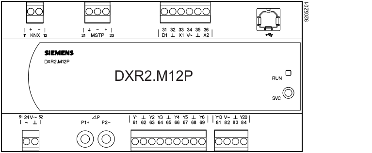
Terminal | Symbol | Description | Module | Channel |
|---|---|---|---|---|
21...23 MS/TP |
| MS/TP connection |
|
|
11, 12 KNX | +, - | KNX connection |
|
|
31...36 inputs | D1 | Digital input | 1 | 1 |
X1, X2 | Universal input | 1 | 5, 6 | |
⏊ | System zero |
|
| |
V~ | Field supply AC 24 V for active sensors |
|
| |
USB |
| USB interface |
|
|
51...52 power 24 V~ | V~ | Power SELV / PELV AC 24 V |
|
|
⏊ | System neutral (always ground to the transformer) |
|
| |
61...69 Triacs | Y1...Y6 | Switching output AC 24 V | 11 | 1...6 |
⏊ | System zero |
|
| |
81...84 analog outputs | Y10, Y20 | Positioning output DC 0...10 V | 21 | 1, 2 |
⏊ | System zero |
|
| |
V~ | Field supply AC 24 V |
|
| |
ΔP differential pressure detector | P1+ | Connected to the higher pressure | 31 | 1 |
P1- | Connected to the lower pressure | 31 | 1 | |
Service | SVC | Service button |
|
|
Display | RUN | Operation LED |
|
|
 , +, -