Supply air VAV box, pressure dependent control (VavSu15)
| This application function operates the modulation of a damper. The resulting change of the air volume flow is pressure dependent. The damper position is calculated based on request signals (from the room controllers) received for heating, cooling and ventilation. In this AF, duct area is for user reference only; it is not used for damper position calculation. There is no coefficient object or coefficient calculation logic. There is an optional collection input for condensation detection at chilled beam(s) or chilled ceiling(s). Air balancing functions are provided by manually changing min and max damper position setpoints. |
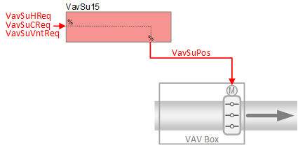
Required elements and how to configure them:
Element | I/O | Signal type |
|---|---|---|
VavSuPos "Setpoint for supply air VAV position" | On-board output, Setpoint for supply air VAV position | 0…10V or 3-position |
or KNX PL-Link device, Supply air VAV | Position control |
Function
The figure below shows BACnet objects associated with this application function. Primary signal flow is summarized as follows:
VAV supply heating, cooling, or ventilation request (VavSuHReq / VavSuCReq / VavSuVntReq) is received and processed into the output signal (in percent) for VAV supply damper position (VavSuPos).
Basic function: Accept request signal from associated room controller and map it to damper position setpoint; Pass result through a device mode logic switch prior to outputting as a command to the object that controls the supply damper position.
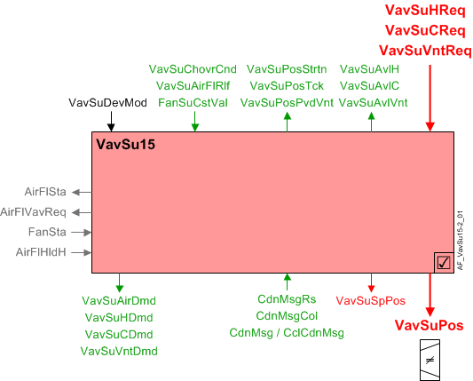
| Command or request (or related) |
| Notification of condition or status, or availability |
| Device mode |
| Interlock (internal signal, not a BACnet object; see Interlocks section for additional information) |


Interlocks
Room automation interlocks are internal signals that coordinate interaction between HVAC devices. They are not visible in ABT Site or web interface, but parameters associated with them are. See comment column for hints on parameters that affect interlock functionality.
Signal | Type | Direction | Description | Comment |
|---|---|---|---|---|
AirFlCReq | Boolean | In | Air flow cooling request |
|
AirFlHReq | Boolean | In | Air flow heating request |
|
AirFlHldH | Boolean | In | Air flow hold for heating |
|
AirFlSta | Boolean | Out | Air flow status | See Configuration section for parameters named "...AirFlSta" |
AirFlVavReq | % | Out | Air flow vav request | Fan-powered box application. |
FanSta | Boolean | In | Fan state | In series fan-powered box applications, parameter EnMonFanSta must = Yes. See Configuration section for additional information. |
Damper position setpoint selection: In control mode (VavSuDevMod = 2) the damper position setpoint (VavSuSpPos) is the largest of the values needed to satisfy the requests for:
- Cooling
- Heating
- Ventilation
- Air flow support for cooling coil
- Air flow support for heating coil
Each request is expressed as a percent value, from 0 to 100%. The percent values are separately mapped to their respective damper positions for heating, cooling, and ventilation. Since damper limits (minimum and maximum) can be / are different for each of the request types, a comparison must be made to select the actual maximum demand (selecting the highest initial percent value among request signals will not necessarily yield the maximum demand signal).
Example:
- Assume damper position limits for cooling as min flow 10% and max flow 80%, resulting in a scale range of 70 (80 - 10 = 70). In this case, a cooling request signal of 50% results in a mapped damper position of 45%. (70 * 0.5) + 10 = 45
In the equation, "70" represents the scale range for damper excursion; "0.5" is the multiplier for a 50% cooling request signal; "10" represents the start position (minimum flow 10%) of the scale range. - Assume damper position limits for ventilation as min flow 15% and max flow 80%, resulting in a scale range of 65 (80 - 15 = 65). In this case, a ventilation request signal of 48% results in a mapped damper position of 46.2%. (65 * 0.48) + 15 = 46.2
46.2% is larger than the mapped cooling position of 45% above, despite what appears to be a smaller initial request signal for ventilation (48%) than for cooling (50%).
The mapping includes a step-up at the low end, with a switch-on point of 4% and a hysteresis of 2%.
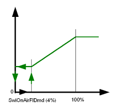
Potential uses of the step-up include:
- Keeping the damper position setpoint high enough to support heat transfer from a coil
If VavSuSpPos is in normal priority and receives a signal of less than 2%, the value of VavSuSpPos will be 0%. The value will stay at 0% until the signal to VavSuSpPos rises above 4%, at which time the value of VavSuSpPos will equal the signal. Between 2% and 4% (hysteresis) VavSuSpPos retains the last value.
Damper position rate change limiter: A rate change limiter function is provided to minimize rapid damper repositioning if the damper is changed by a large amount (for example, manually by a user). The rate limiter delay (default 60sec) is only applied when VavSuSpPos is in normal runtime priority – not protection or emergency priority.
Saturation signal: The saturation signal VavSuPosStrtn is a binary object that is True ("Starved") when the VAV supply air terminal cannot get enough air for a time exceeding a built-in time delay.
Note
VavSuPosStrtn is always Off if parameter EnStrtnCal = 0 (No). This allows the user to exclude a particular terminal from the saturation pressure reset system.
Relief input signal: A VAV box’s binary air flow relief object (VavSuAirFlRlf) can be set to True by the air handling unit. This is done to relieve flow resistance in the duct system in order to maintain proper static pressure.
When device mode = control mode and both EnRlf (Enable relief) and VavSuAirFlRlf equal On, VavSuSpPos will not go below the value of the damper relief parameter (PosRlf).
Note
Relief has no effect on the supply chain VAV air demand signal VavSuAirDmd.
Available status: When the VAV supply damper is available for heating or cooling or ventilation, the respective binary output signal(s) that indicate availability (VavSuAvlH, VavSuAvlC, VavSuAvlVnt) will be "Yes" (available).
For available status to be "Yes", device mode must equal "Control mode" (modulation) and VavSuChovrCnd (Supply air VAV changeover condition) cannot equal "Neither".
The output signal VavSuPosPvdVnt is the amount of air flow available for ventilation. When VavSuAvlVnt is True, a maximum value (VavSuPosMaxVnt) is transferred to VavSuPosPvdVnt. VavSuPosPvdVnt is the largest max flow (damper position) of the supply VAV boxes. These values are set in each supply VAV for the maximum flow in the segment.
Minimum ventilation flow: In an installation without DCV (demand control ventilation), the minimum primary air flow is applied whenever ventilation is required. This effectively replaces minimum cooling and minimum heating values. In an installation with DCV, the primary air flow value is applied when the calculated ventilation demand is at minimum and ventilation is required.

See the room level ventilation control AF (VavVntCtl.xx) for detailed information on configuring minimum ventilation levels.
Device mode: The input signal for device mode is a multistate value.
VavSuDevMod supports the following states:
- Off
- Control mode (modulation)
- Max.air vol.flow
- Min.air vol.flow
- Smoke ctrl.air flow setp (manually entered damper setpoint value for smoke control)
When device mode = Min.air vol.flow:
- If VavSuChovrCnd (Supply air VAV changeover condition) is Neither,
then VavSuSpPos = VavSuPosMinVnt (Supply air VAV min.position for vent) - If VavSuChovrCnd is Heating, then VavSuSpPos = VavSuPosMinH
- If VavSuChovrCnd is Cooling, then VavSuSpPos = VavSuPosMinC
- If VavSuChovrCnd is Neutral, then VavSuSpPos = greater of VavSuPosMinH or VavSuPosMinC
Fan coasting feature: The fan coasting feature prevents premature closing of the room supply damper while the AHU fan is coasting down. This might occur during a switch between operating modes (for example, switching from Comfort to Economy).
The fan coasting feature is active when:
- The room supply air damper is the only damper that is open – all other VAV supply air dampers are closed.
- The AHU supply fan has been turned off and is coasting down.
- The air flow setpoint signal (VavSuSpAirFl), while on its way to zero, falls below the air flow demand hysteresis setting (HysAirFlDmd).
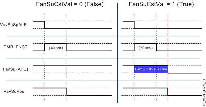
When these conditions are true, the boolean supply fan coasting signal (FanSuCstVal) will equal 1 (True) and the damper is reset to its last (previous) operating position / value. This keeps the damper open while the fan coasts down to prevent supply duct over-pressure.
In addition to the fan coasting signal freezing the damper in place, an internal timer function was activated when VavSuSpAirFl initially dropped below HysAFlSta. The fan coasting signal and the timer (60 seconds) must both finish (return to False) before the room supply damper can close. See the figure below.
Note
The internal timer operates independently and regardless of FanSuCstVal. Once the timer is activated, the room supply air damper is frozen in place until the counter reaches zero, after which the damper may close.
Supply chain interface: There are four demand output signals for air.
- VavSuCDmd - Supply air VAV cooling demand
When cooling is available, VavSuCDmd is the percentage value of the cooling request from the room (otherwise it is 0). - VavSuHDmd - Supply air VAV heating demand
When heating is available, VavSuHDmd is the percentage value of the heating request from the room (otherwise it is 0). - VavSuVntDmd - Supply air VAV ventilation demand
When ventilation is available, VavSuVntDmd is the percentage value of the ventilation request from the room (otherwise it is 0). - VavSuAirDmd - Supply air VAV air demand for plant mode
VavSuAirDmd is a multistate value that equals PltOpMod (VavSuSpPos must be greater than the switch-on point for air flow demand. If PltOpMod is "Depressurize" or "Emergency off", VavSuAirDmd will equal PltOpMod regardless of VavSuSpPos value.
AHU changeover condition signal: The multistate VAV supply changeover condition input signal (VavSuChovrCnd) comes from the room coordinating function (RCoo). It indicates the current heating / cooling available status for central AHU. Four states are supported:
- Neither
- Heating
- Cooling
- Neutral
"Neutral" means that heating and cooling PID controllers are both enabled and that the system is providing air that is not hot or cold.
Configuration
 Objects
Description | Object | Type | Default value |
|---|---|---|---|
Duct | |||
Supply air VAV duct area | VavSuDuctArea | ACnfVal | 0.05 [m2] |
Supply air VAV duct shape 1:Rectangular | VavSuDuctShape | MCnfVal | 2:Round |
Supply air VAV dimension A | VavSuDmsnA | ACnfVal | 20 [cm] |
Supply air VAV dimension B | VavSuDmsnB | ACnfVal | 20 [cm] |
Air flow settings | |||
Supply air VAV smoke control setpoint position | VavSuSpPosSmk | ACnfVal | 50 [%] |
Supply air VAV maximum position for cooling | VavSuPosMaxC | ACnfVal | 100 [%] |
Supply air VAV minimum position for cooling | VavSuPosMinC | ACnfVal | 50 [%] |
Supply air VAV maximum position for heating | VavSuPosMaxH | ACnfVal | 100 [%] |
Supply air VAV minimum position for heating | VavSuPosMinH | ACnfVal | 50 [%] |
Supply air VAV maximum position for ventilation | VavSuPosMaxVnt | ACnfVal | 100 [%] |
Supply air VAV mininimum position for ventilation | VavSuPosMinVnt | ACnfVal | 0 [%] |
 Parameters
Description | Parameter | Default value |
|---|---|---|
Setpoint selector for extract air VAV box 0:Setpoint for supply air VAV position | SpSelVavEx | 1:Supply air VAV position |
Interlocks | ||
Switch-on point for position state | SwiOnPtPosSta | 10 [%] |
Hysteresis for position state | HysPosSta | 5 [%] |
Enable monitoring for fan state 0:No | EnMonFanSta | 0:No |
Rate limitation for position | RateLmPos | 60 [s] |
Saturation calculation | ||
Enable saturation calculation Saturation signal calculation logic: 0:No | EnStrtnCal | 1:Yes |
Saturation level | StrtnLvl | 90 [%] |
Switch-on delay saturation | DlyOnStrtn | 60 [s] |
Position demand | ||
Switch-on point for position demand | SwiOnPtPosDmd | 4 [%] |
Hysteresis for position demand | HysPosDmd | 2 [%] |
Relief functionality | ||
Enable relief 0:No | EnRlf | 0:No |
Position relief | PosRlf | 50 [%] |
Interface
Interface | Description | Type | Ref. | Owned by | |
|---|---|---|---|---|---|
VavSuPos | Supply air VAV position | AO | ◉ | Room segment / Device | |
VavSuSpPos | Supply air VAV setpoint position | APrcVal | ● | - | |
VavSuPosStrtn | Supply air VAV position saturation 0:Satisfied | BCalcVal | ● | 0:Satisfied | |
VavSuDevMod | Supply air VAV device mode 1:Off | MPrcVal | ● | - | |
VavSuCReq | Supply air VAV cooling request | ACalcVal | ● | - | |
VavSuHReq | Supply air VAV heating request | ACalcVal | ● | - | |
VavSuVntReq | Supply air VAV ventilation request | ACalcVal | ● | - | |
VavSuAvlC | Supply air VAV available for cooling 0:No | BCalcVal | ● | - | |
VavSuAvlH | Supply air VAV available for heating 0:No | BCalcVal | ● | - | |
VavSuAvlVnt | Supply air VAV available for ventilation 0:No | BCalcVal | ● | - | |
FanSuCstVal | Coasting value of supply air fan 0:Off | BCalcVal | ● | - | |
VavSuChovrCnd | Supply air VAV changeover condition 1:Neither | MPrcVal | ● | - | |
VavSuAirDmd | Supply air VAV air demand for plant mode 1:Off | MCalcVal | ● | - | |
VavSuAirFlRlf | Supply air VAV air volume flow relief 0:Off | BPrcVal | ● | - | |
VavSuCDmd | Supply air VAV cooling demand | ACalcVal | ● | - | |
VavSuHDmd | Supply air VAV heating demand | ACalcVal | ● | - | |
VavSuVntDmd | Supply air VAV ventilation demand | ACalcVal | ● | - | |
VavSuPosPvdVnt | Supply air VAV position provided for ventilationSupply air VAV position tracking | ACalcVal | ● | - | |
VavSuPosTck | Supply air VAV position tracking | ACalcVal | ● | - | |
CdnMsgCol | Collection of condensation message | ColView | ● | - | |
| CdnMsgRs | Result of condensation message 0:Normal | BCalcVal | ● | - |
CdnMsg | Condensation message 0:Normal | BCalcVal | ◉ | Room segment / Field device | |
CclCdnMsg | Cooling coil condensation message 0:Normal | BCalcVal | ◉ | Room segment / Field device | |
VavSuSplyAir | Supply air VAV supply chain for air | GrpMbr | ● | Room segment | |
VavSuBalSta | Supply air VAV balancing state 1:Initial | MCnfVal | ● | - | |
VavSuDuctArea | Supply air VAV duct area | ACnfVal | ● | - | |
VavSuDuctShape | Supply air VAV duct shape 1:Rectangular | MCnfVal | ● | - | |
VavSuDmsnA | Supply air VAV dimension A | ACnfVal | ● | - | |
VavSuDmsnB | Supply air VAV dimension B | ACnfVal | ● | - | |
VavSuSpPosSmk | Supply air VAV smoke control setpoint position | ACnfVal | ● | - | |
VavSuPosMaxC | Supply air VAV maximum position for cooling | ACnfVal | ● | - | |
VavSuPosMinC | Supply air VAV minimum position for cooling | ACnfVal | ● | - | |
VavSuPosMaxH | Supply air VAV maximum position for heating | ACnfVal | ● | - | |
VavSuPosMinH | Supply air VAV minimum position for heating | ACnfVal | ● | - | |
VavSuPosMaxVnt | Supply air VAV maximum position for ventilation | ACnfVal | ● | - | |
VavSuPosMinVnt | Supply air VAV mininimum position for ventilation | ACnfVal | ● | - | |
Engineering and commissioning
- Check for correct damper actuator installation. Actuator mis-wiring or improper installation is a major cause of common problems.
- VavSuSplyAir Group Member – provides information to the central AHU for duct static pressure reset:
RHvacCoo_xx contains a GroupMember (SplyAir) that monitors/receives data from the central function SplyAir group manager. The central function should be located in the room automation station that contains ALL central coordination functions that come from rooms (e.g., child) serviced by the central system (e.g., parent). Verify the assignment of the group numbers in the group manager objects and in the assigned group member objects. Make sure that the group numbers of the group managers in the same group category are unique on the network.
See the room level ventilation control AFs (VavVntCtl, FcuVntCtl) for detailed information on configuring minimum ventilation levels.