Performing program simulation
A program can be simulated to test its logical workflow.
|
|

PXC4.E16.A and PXC7.E400.A do not support engineering, programming and simulation. For more information, check the corresponding hardware documentation of the device.
Scope of simulation
- Simulation of program code without any system hardware, field devices or racks can be performed in order to ad-hoc verify functionalities such as:
- Release/hold functions
- Sequence of operation
- Startup/shut-down functions
- Emergency functions
- Simulation works with BACnet objects. Modbus devices or other field devices cannot be simulated.
- Simulation can be performed:
- in the office without hardware installation
- on site without interfering with the running installation process.
- Simulation is possible for
- I/O editor
- Modbus editor
- Programming editor
- Web interface
- Connected BACnet clients, such as Desigo CC or Desigo Control Point
PC requirements for simulation: At least 16 GB RAM, SSD with 500 MB for simulation per device type (e.g., PXC4/5/7) needed.
Perform a program simulation
- Only IP devices are supported.
- Only one program simulation at a time is possible.
- Simulation configuration of the device is saved automatically once  Pause or Stop simulation is clicked. When starting the simulation again, saved values are restored.
- Firmware upgrade is not supported in simulation.
- If there is no activity during a longer simulation period, the simulation is stopped after the set auto-logoff delay. The auto-logoff time delay can be set between 5 to 60 minutes.
Settings > User profiles > Users > [User name] > Auto-logoff delay
Users
1. Start the simulation mode
- The auto-logoff delay is set to extended simulation.
Users - A PXC4/5/7 device is added and configured in Building > Building structure.
- The certificate type on the device is set to Internal.
- Go to Building > Building structure or, alternative, go to Application & device overview.
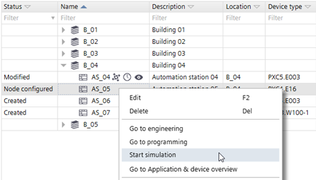
- Right-click the device and select Start simulation.
- Go to Startup.
- Select the offline device (for which simulation is started) in Engineered devices tab.
- Select the online device in Discovered devices tab.
- The connection status changes from
 to
to  .
. - Click Assign.
- The online device will be configured with offline device data.
- Select Engineered devices tab.
- Right-click the device and select Load > Full (device may restart).
- The virtual device is ready for simulation.

- In the Engineering tab, click
 Play to perform the play operation in the I/O Configuration or Modbus editor.
 - The device goes online.
- The Simulation tab displays on the right.
Error message:IP address xxx.xx.x.xxx already used in the network. Change the device IP address in the project.
1. In Windows, select Control Panel\Network and Internet\Network Connections.
2. Select the ABTSimulation VPN network.
3. Right-click and select Properties.
4. Change the IP address to resolve the conflict.
2. Configure the simulated data point
- Select a data point.
- Go to the Simulation tab on the right.
- Configure the signal value as needed. Refer to the subchapter to the corresponding data point type.
In simulation mode, you can set or modify values. For each object type, there is a signal source: - Analog: Constant, Sine, Feedback
- Binary: Constant, Feedback, Toggle
- Multistate: Constant, Feedback, Split into binaries
Examples of program configuration
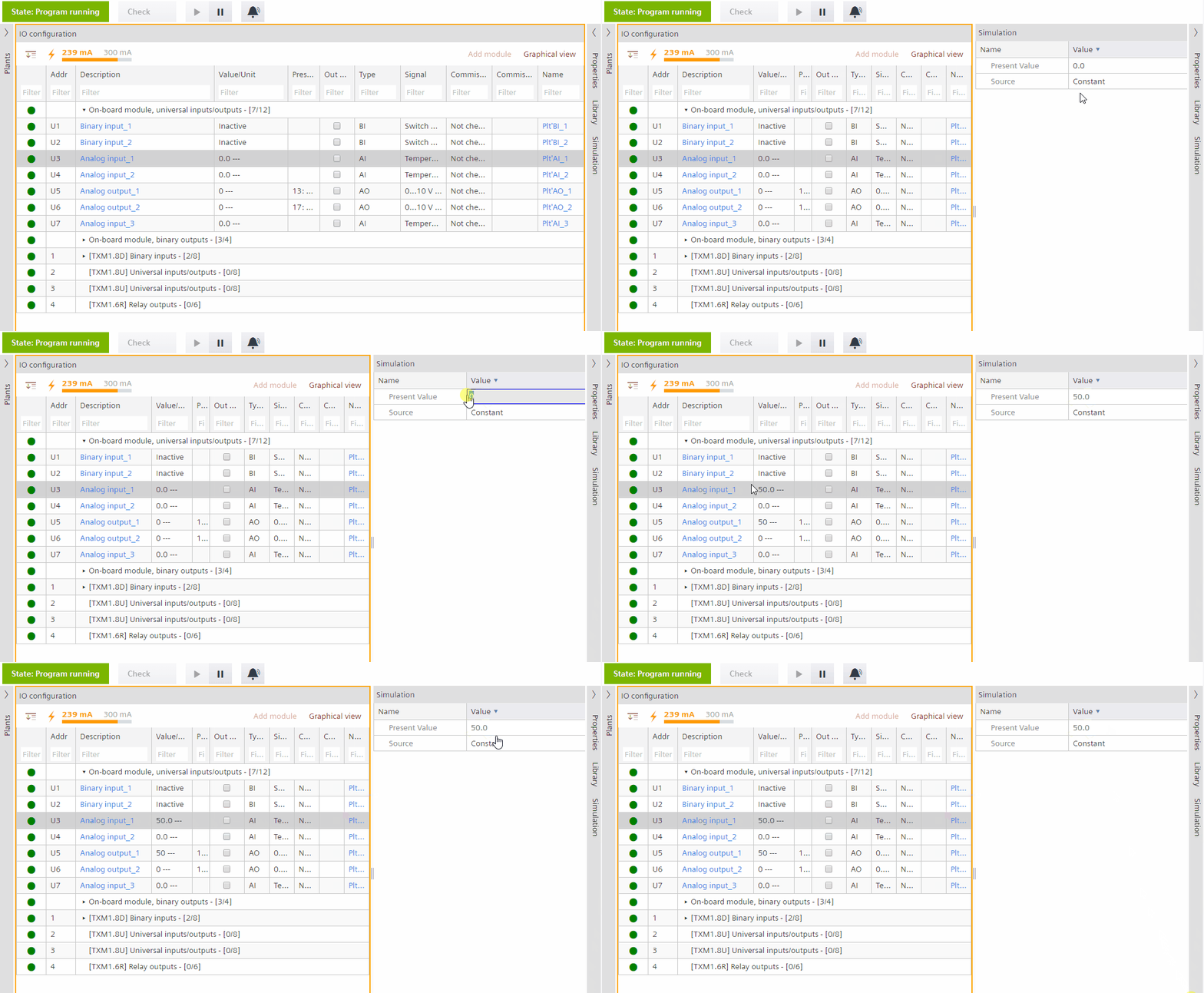
Constant is a function that allows an input signal (binary input, analog input, multistate input objects) to set a constant value.
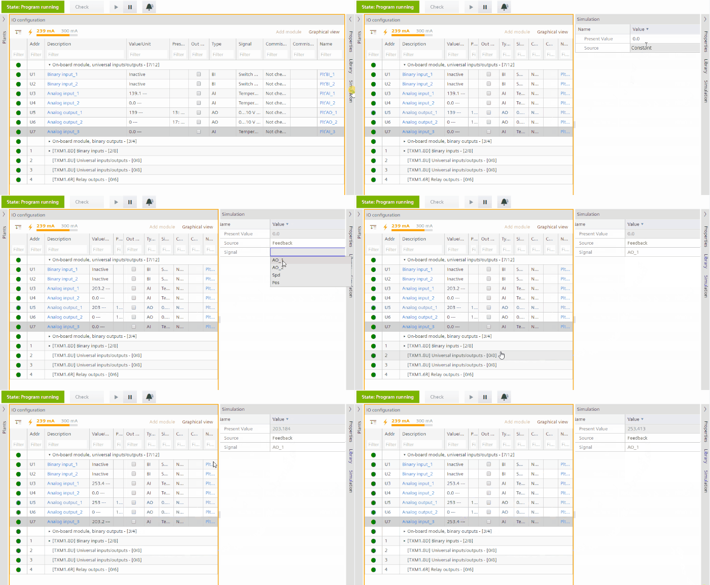
Feedback is a function that allows an input signal (Binary input, multistate input, analog input objects) to replicate the current value of a given output signal.
Available configuration properties:
Signal: Drop down menu with the following functionality for the different signal types:
- Binary input (BI): All available binary outputs (BO) in the device are displayed. The BI value then becomes equal and updated constantly to match the BO value.
- Analog input (AI): All available analog outputs (AO) in the device are displayed. The AI value then becomes equal and updated constantly to match the AO value.
- Multistate input (MI): All available multistate outputs (MO) in the device are displayed. The MI value then becomes equal and updated constantly to match the MO value.
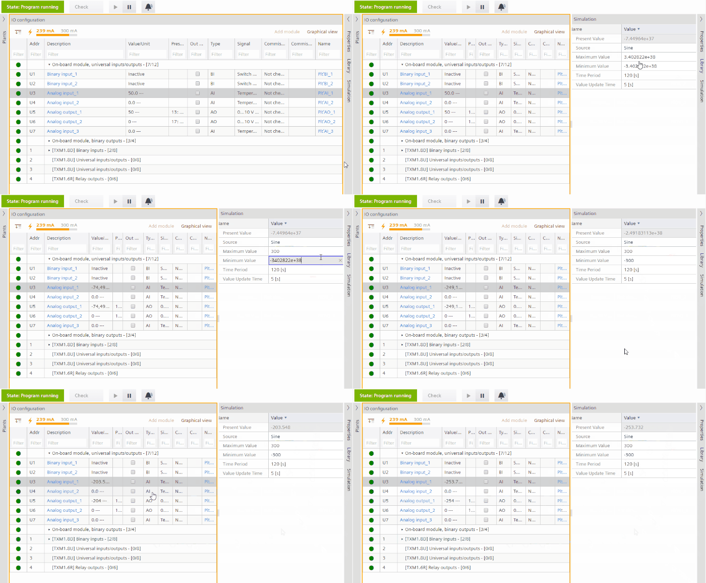
Sine wave is a function that allows to simulate a sine wave behavior for analog input (AO) signals.
Available configuration properties:
- Value update time shows how many steps are performed from min. to max.
- Max. value: Peak of the sine wave function. Must always be bigger than min. value.
Default = 10; max value = signal maximum.; min. value = signal minimum. - Min. value: Bottom of the sine wave function. Must always be less than max. value.
Default = 10; max value = signal maximum.; min. value = signal minimum. - Time period: Shows how much time it takes for one full cycle of the sine wave.
Time period default = 120 sec.; time period min. = 10 sec.; time period max. = 100.000 sec. - Value update time: How often the PrVal of the object is updated. Shows how many steps are performed for one full cycle of the sine signal.
Time period = 10 sec/value update time = 1 (10 values for PrVal for one cycle updated every sec.);
Time period = 10 sec./value update time = 2 (5 values for PrVal for one cycle updated every 2 sec.);
Default = 5 sec.; max. value = 1.000 sec.; min. value = 1 sec.
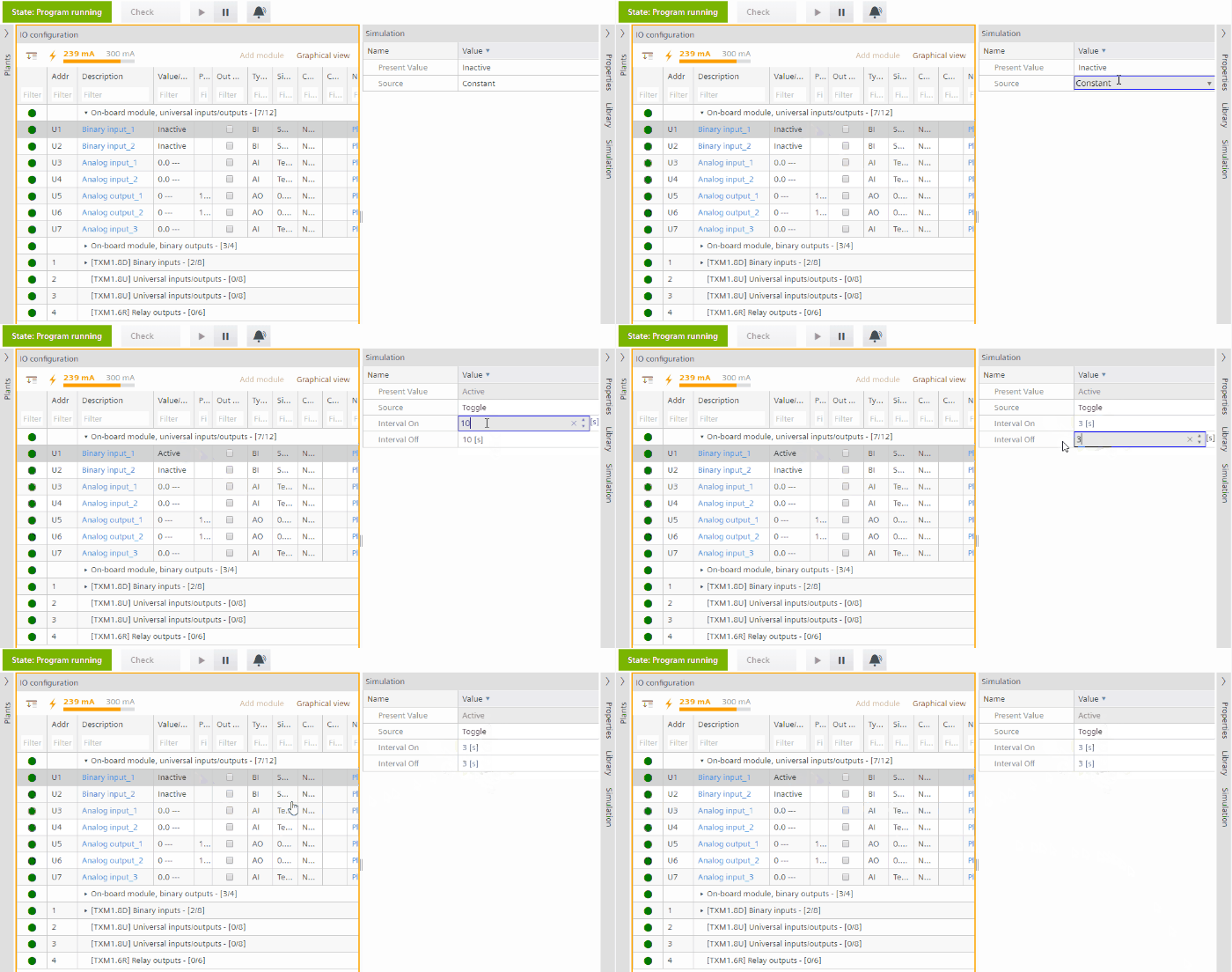
Binary signal is a simple function for toggling a binary input (BO) object from value 0 to 1 and vice versa with a configurable delay between the two signals.
Available configuration properties:
- Interval On: determines the time the signal value is 1. Default = 10 sec.; Max. = 10.000; Min. = 0.
- Interval Off: determines the time the signal value is 0. Default = 10 sec.; Max. = 10.000; Min. = 0.
Different binary output (BO) signals simulate a multistate input (MI).
- Simulation mode is active.
- Configuration is setup with a multistate input and the number of binary outputs.
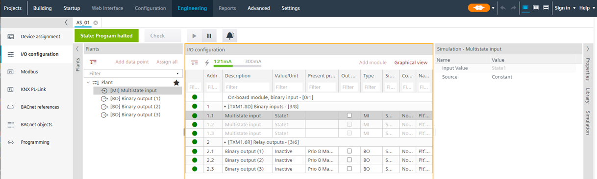
- Select the multistate input data point.
- Select the Simulation tab.
- From the Source drop-down list, select SplitintoBinaries.
- From the State1 drop-down list, select the corresponding binary output.
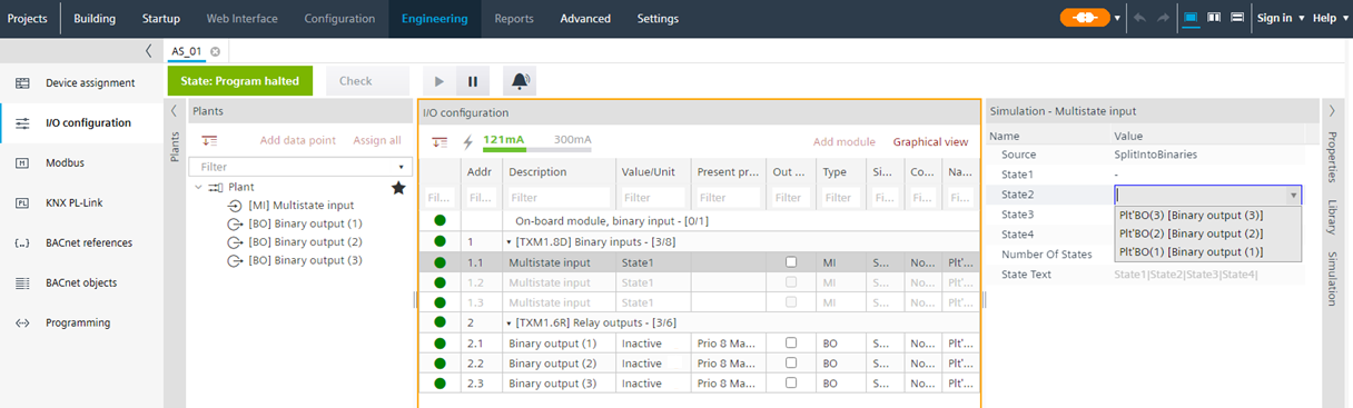
- Enter the data for state 2-n.
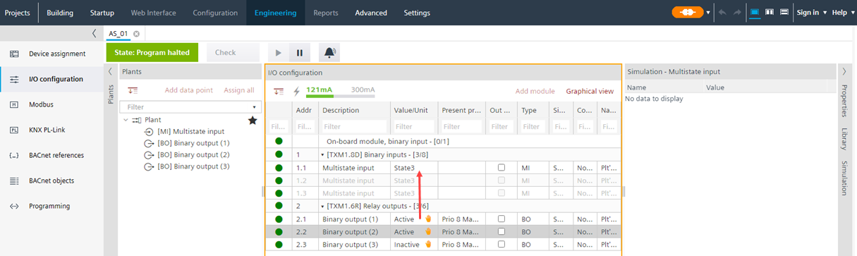
- In the Value/Unit column, select a binary output.
- From the binary output drop-down list, select Active.
- The override icon displays.
- The status of the multistate input changes in the Value/Unit column.
3. Test the application
- Go to the Programming editor and click on Play to perform the play operation.
- Verify the program functionality (e.g., sequence of operation)
- In case a program change is needed:
a. ClickPause.
b. Modify the application functionality.
c. ClickPlay again.
d. Verify the program changes. - Click Pause and go back to Building > Building structure.
- Right-click the device and select Stop simulation.
Use connected BACnet clients
To use connected BACnet clients for simulation, you must add separate IP addresses to the network.
- In Windows:
- Go to Settings > Network & Internet.
- Right-click the network adapter.
- Click Properties > IP settings.
- Select Internet Protocol Version 4 (TCP/IPv4).
- Click Properties and enter an IP address.
After ending the simulation, a full load of the target hardware is required.
In case a virtual environment such as VMware or Hyper-V is used for the simulation, ABT Site and all clients must be included in the same VMware image.
It is not recommended to perform the simulation in a virtual environment.