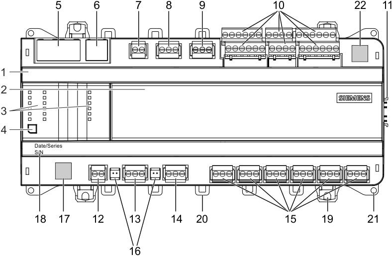
PXC5.E24
|
| 8 | Plug-in terminal block with screw terminals | |
9 | Plug-in terminal block with screw terminals | ||
10 | Plug-in terminal blocks with screw terminals | ||
11 | Connector for I/O modules TXM | ||
12 | Plug-in terminal blocks with screw terminals | ||
13 | Plug-in terminal block with screw terminals COM1 interface COM2 interface | ||
15 | Plug-in terminal block with screw terminals | ||
16 | DIP switches for bus termination and polarization COM | ||
1 | Plastic housing | 17 | QR code for default WLAN access |
2 | Battery cover | 18 | Date / series and serial number |
3 | LEDs for communication, state, and relays | 19 | Slider for mounting on DIN rails |
4 | Service button (ID on network and WLAN on/off) | 20 | Eyelets for cable ties |
5 | LAN: 2-port Ethernet switch with 2 LEDs per port for display purposes | 21 | Holes for wall mounting |
6 | WAN: Ethernet port with 2 LEDs for display purposes | 22 | Data matrix code |
7 | Plug-in terminal block with screw terminals | ||
Activity | LED | Color | Activity | Function |
|---|---|---|---|---|
|
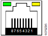
| Ethernet 1A/1B | Green | Steady ON | Link active |
Yellow | Steady ON | Link 100 Mbps | ||
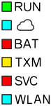
| RUN | Green | Steady ON | Device operational |
Red | Steady OFF | OK | ||
| Blue | Steady ON | Cloud connection OK | |
BAT | Red | Steady OFF | Optional battery OK | |
TXM | Yellow | Flashing | Communication | |
SVC | Red | Steady OFF | OK | |
Flashing after wink command | Device ID after receipt of wink command | |||
| ||||
WLAN | Blue | Steady OFF Steady ON Flashing | WLAN inactive WLAN active and at least one WLAN client connected WLAN active and no WLAN client connected | |
| COM… | Yellow | Flashing | Communication |
KNX | Yellow | Flashing | Communication | |
MBUS | Yellow | Flashing | Communication | |
| DO... | Yellow | Steady OFF Steady ON | I/O status OFF I/O status ON |

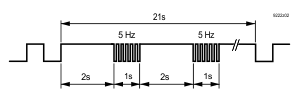
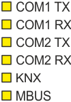
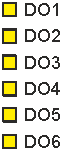
Activity | LED | Color | Activity | Function |
|---|---|---|---|---|
|
| Service button |
| Press 0.2 ... 1 s Press 1 ... 3 s | ID in the network WLAN enable/disable |
Factory reset |
|

|
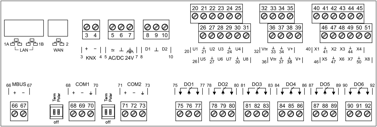
Terminal | Symbol | Description | Module | Channel |
1A, 1B |
| LAN: 2 x RJ45 interface for Ethernet with switch |
|
|
2 |
| WAN: 1 x RJ45 interface Note: WAN port does not support BACnet/SC connections |
|
|
3, 4 | KNX | KNX PL-Link |
|
|
5, 6 | ≃, ⏊ | Operating voltage AC 24 V or DC 24 V |
|
|
7 |
| Functional ground (must be connected on the installation side with the building grounding system (PE)). |
|
|
8, 10 | Dx | Digital inputs 1…2 | 71 | 1…2 |
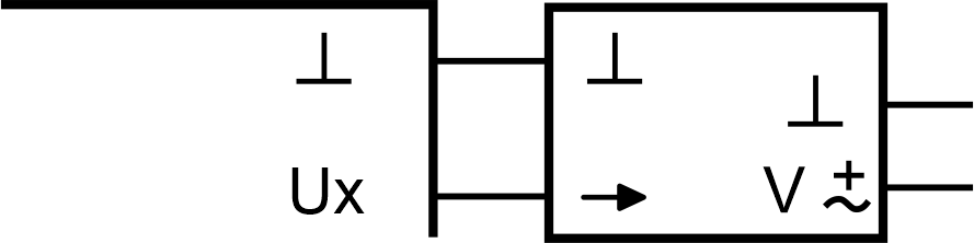
20 to 31 | Ux | Universal inputs / outputs 1…8 | 61 | 1…8 |
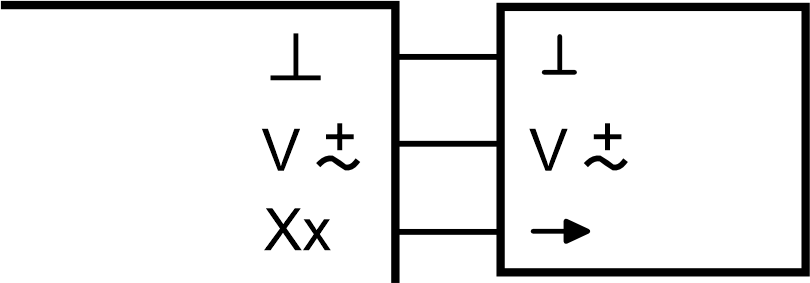
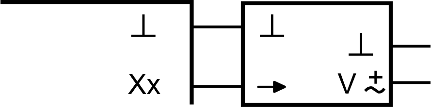
40 to 51 | Xx | Super universal inputs / outputs 1…8 | 62 | 1…8 |
| ⏊ | Measuring ground for Ux and Xx |
|
|
32, 36 | V≃ | AC 24 V power for field devices 48 VA / 2 A |
|
|
35, 39 | V+ | DC 24 V power for field devices 4.8 W / <200 mA |
|
|
66, 67 | MBUS | M-bus interface |
|
|
68, 69, 70 | COM1 | Interface EIA-485 (M-bus, Modbus RTU, BACnet MS/TP) |
|
|
71, 72, 73 | COM2 | Interface EIA-485 (M-bus, Modbus RTU, BACnet MS/TP) |
|
|
Term | on, off | Switch for bus termination |
|
|
Polar | on, off | Switch for polarization |
|
|
75 to 92 | DOx | Relay outputs 1…6 | 11 | 1…6 |
Right side of device |
| Interface for connecting TXM I/O modules |
|
|


Wiring lines for field devices
Wiring length max. 300 m (1,000 ft), CU wire or CU strand.
Cross-section depending on the signal
30 m (100 ft) applies for signal types AI NTC10K and AI NTC100K
or 300 m (984 ft) with shielding
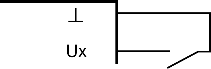
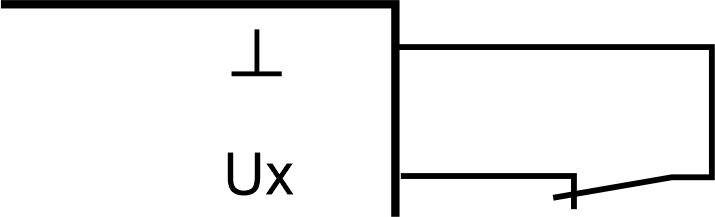
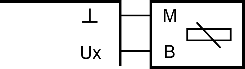
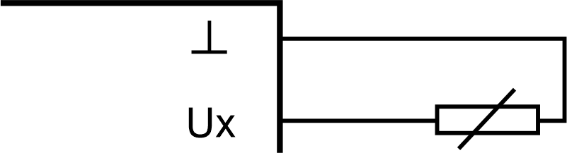
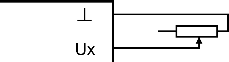
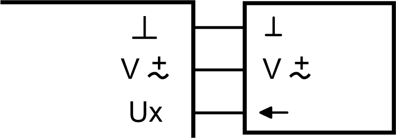
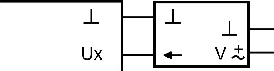
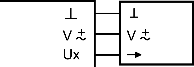
Examples of connection diagrams for universal inputs/outputs
|
Digital inputs |
|
|
|
|
|
| |
Count inputs: | Counter inputs, that count faster than 1 Hz and are laid with more than 10 meters using analog inputs in the same cable duct, must be shielded. | ||
|
Analog inputs |
|
|
|
|
|
| |
|
|
| |
|
|
| |
|
|
| |
|
|
|

|
Analog outputs |
|
|
|
|
|
| |
|
|
| |
|
|
| |
|
|
| |
|
|
|


|
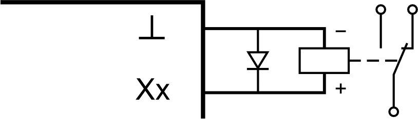
Off-board relay outputs |
|
|
|