CONT_4ST: Step switch for 4 stages
The CONT_4ST (FB418) block determines the resultant switching stage for a multistage aggregate in dependence of an analog input value.
There are four switch-on thresholds and four hystereses.
Functionality
The block determines the requested "Setpoint stage" [SpSt] from the analog value [In].
If the direction of control action is direct ([Actg] = 0 (Direct)), a higher stage is requested for an increasing input value [In]. The switch-on thresholds are then parameterized in the following order: [SwiOnPt1] < [SwiOnPt2] < [SwiOnPt3] < [SwiOnPt4].
The requested "Setpoint stage" [SpSt] is 1, if [In] ≥ [SwiOnPt1]. The stage is 2, if [In] ≥ [SwiOnPt2] etc. The steps are reset only if [In] is below the switch-on points [SwiOnPt1]...[SwiOnPt4] - hysteresis [Hys1]...[Hys4]. The block orders the switch-on points accordingly if these sequence is not maintained.
If the direction of control action is reversed ([Actg] = 1 (Reverse)), a lower stage is requested for an increasing input value [In]. The switch-on points are then parameterized in the following order: [SwiOnPt4] < [SwiOnPt3] < [SwiOnPt2] < [SwiOnPt1].
The requested "Setpoint stage" [SpSt] is 1, if [In] ≤ [SwiOnPt1]. The stage is 2, if [In]≤[SwiOnPt2], etc. The steps are reset only if [In] is above the switch-on points [SwiOnPt1]...[SwiOnPt4] - hysteresis [Hys1]...[Hys4]. The block orders the switch-on points accordingly if these sequence is not maintained.
The offset [Ofs] allows for adding an additional value to [SpSt].
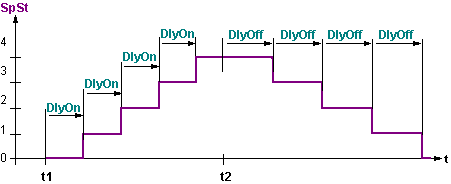
Switching on and off is delayed ([DlyOn], [DlyOff]). The switch-on or switch-off delays are set for each stage. Only one stage can be switched on or off at a time.
Additionally, a minimum runtime per stage [TiRnMin] and a minimum pause time per stage [TiOffMin] can be parameterized. These times cause the stage to run for at least the indicated time after switch-on or to be switched off for at least the indicated time.
If the output reaches the highest stage (by including the switch-on delay and the minimum pause time), output [ReqHi] = 1 (Yes).
If the block is fully reset (by including the switch-off delay and the minimum switch-on time), output [ReqLo] = 1 (Yes).
The block function can be fully disabled via [EnFnct] = 0 (No). When [EnFnct] = 0 (No), the output [SpSt] and all times are reset regardless of a possibly started minimum runtime. When [EnFnct] = 1 (Yes), the function is enabled.
[EnHi] = 1 (Yes) enables step-up.
[EnLo] = 1 (Yes) enables step-down.
Output control [SpSt] at [EnFnct] = 1 (Yes).
Switch-on and switch-off delays and minimum times are not considered in this table; they take priority over control by [In], i.e., changeover occurs only after the times have expired.
The indication "load" in the table means that the block output remains at the value set prior to the input value entering this range.
Response for [Actg] = 0 (Direct).
IF In ≥ SwiOnPt4 | Out = 4 + Ofs |
ELSEIF In ≥ SwiOnPt4 – Hys4 AND Last = 4 | Out = 4 + Ofs |
ELSEIF In ≥ SwiOnPt3 | Out = 3 + Ofs |
ELSEIF In ≥ SwiOnPt3 – Hys3 AND Last = 3 | Out = 3 + Ofs |
ELSEIF In ≥ SwiOnPt2 | Out = 2 + Ofs |
ELSEIF In ≥ SwiOnPt2 – Hys2 AND Last = 2 | Out = 2 + Ofs |
ELSEIF In ≥ SwiOnPt1 | Out = 1 + Ofs |
ELSEIF In ≥ SwiOnPt1 – Hys1 AND Last = 1 | Out = 1 + Ofs |
ELSE | Out = 0 + Ofs |
END | --- |
Response for [Actg] = 1 (Reverse).
IF In ≤ SwiOnPt4 | Out = 4 + Ofs |
ELSEIF In ≤ SwiOnPt4 + Hys4 AND Last = 4 | Out = 4 + Ofs |
ELSEIF In ≤ SwiOnPt3 | Out = 3 + Ofs |
ELSEIF In ≤ SwiOnPt3 – Hys3 AND Last = 3 | Out = 3 + Ofs |
ELSEIF In ≤ SwiOnPt2 | Out = 2 + Ofs |
ELSEIF In ≤ SwiOnPt2 – Hys2 AND Last = 2 | Out = 2 + Ofs |
ELSEIF In ≤ SwiOnPt1 | Out = 1 + Ofs |
ELSEIF In ≤ SwiOnPt1 – Hys1 AND Last = 1 | Out = 1 + Ofs |
ELSE | Out = 0 + Ofs |
END | --- |
If the four possible stages or aggregates are insufficient, several CONT_4ST blocks can be switched in sequence. In this case, the delay times can be used for each individual block (e.g. two separate, 4-stage E-heating coils) or for several blocks (e.g. 8-stage heating coils).
Diagrams
Diagram 1: Example for [Actg] = 0 (Direct) and [Ofs] = 0.
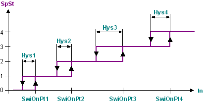
Diagram 2: Example for [Actg] = 1 (Reverse) and [Ofs] = 0.
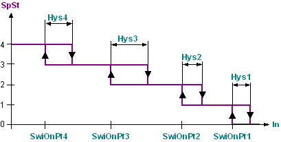
Diagram 3: Time response of input and output delays.
At t1, [In] moves from ≤[SwiOnPt1] to [SwiOnPt4].
At t2, [In] moves from [SwiOnPt4] to ≤ [SwiOnPt1] - [Hys1].
Inputs
Pin | E | Description |
EnFnct | p | Enable function. 1 (Yes): The function is enabled. 0 (No): The function is disabled. |
In | pa | Input. Value used to derive the switching state. |
SwiOnPt1 | pa | Switch-on point 1. Switching threshold for switch-on for stage 1. |
Hys1 | pa | Hysteresis 1. Hysteresis for stage 1. |
SwiOnPt2..4 | pa | Switch-on point 2..4. Switching threshold for switch-on for stages 2..4. |
Hys2..4 | pa | Hysteresis 2..4. Hysteresis for stages 2..4. |
Actg | pa | Direction of control action 0 (Direct): Switch-up at increasing input signal. 1 (Reverse): Switch-down at increasing input signal. |
DlyOn | pa | Switch-on delay. Waiting time until the stage is actually switched after the stage request has been sent out. |
DlyOff | pa | Switch-off delay. Waiting time until the stage is actually switched off after the stage request reset has been sent out. |
TiRnMin | pa | Minimum runtime. Minimum time during which an enabled stage must be switched on. |
TiOffMin | pa | Minimum switch-off time. Minimum time during which a disabled stage must be switched off. |
EnHi | pa | Enable step-up. 1 (Yes): (Default value). |
EnLo | pa | Enable step-down. 1 (Yes): (Default value). |
Ofs | pa | Offset. Fixed value added to the output [SpSt]. |
NumSts | pa | Number of stages. Number of possible stages or number of switchable aggregates. The number of possible switching stages must be parameterized. |
Outputs
Pin | E | Description |
SpSt | a | Setpoint stage. Required stage as an integer to switch a multi-step aggregate. |
ReqHi | a | Request higher. Highest possible switching stage or last aggregate reached. |
ReqLo | a | Request lower. Switching stage Off reached or all aggregates switched off. |
Input values
Pin | Description | Data type | Default value | E.g. Engineering unit or Text group | Min. | Max. |
EnFnct | Enable function. | Boolean | 1 (Yes) | No, Yes |
|
|
In | Input. | Real | 0.0 |
| -3.403E38 | 3.403E38 |
SwiOnPt1..SwiOnPt4 | Switch-on point 1..4. | Real | 0.0 |
| -3.403E38 | 3.403E38 |
Hys1..Hys4 | Hysteresis 1..4. | Real | 0.0 |
| -3.403E38 | 3.403E38 |
Actg | Direction of control action | Boolean | 1 (Reverse) | Direct, Reverse |
|
|
DlyOn | Switch-on delay. | Time | 0ms | T#0d_0h_0m_0s_0ms |
|
|
DlyOff | Switch-off delay. | Time | 1m_40s | T#0d_0h_0m_0s_0ms |
|
|
TiRnMin | Minimum runtime. | Time | 1m_40s | T#0d_0h_0m_0s_0ms |
|
|
TiOffMin | Minimum switch-off time. | Time | 0ms | T#0d_0h_0m_0s_0ms |
|
|
EnHi | Enable step-up. | Boolean | 1 (Yes) | No, Yes |
|
|
EnLo | Enable step-down. | Boolean | 1 (Yes) | No, Yes |
|
|
Ofs | Offset. | Integer | 0 |
| 0 | 8 |
NumSts | Number of stages. | Integer | 4 |
| 0 | 4 |
Output values
Pin | Description | Data type | Default value | E.g. Engineering unit or Text group | Min. | Max. |
SpSt | Setpoint stage. | Integer | 0 |
| -32768 | 32767 |
ReqHi | Request higher. | Boolean | 0 (No) | No, Yes |
|
|
ReqLo | Request lower. | Boolean | 0 (No) | No, Yes |
|
|
Operating mode.
EnFnct | Description |
1 (Yes) | Outputs switch as per the description. |
0 (No) | The outputs are switched off and the times reset. |
Use
The block can switch an aggregate in dependence of the analog value in multiple switching steps. These steps are e.g. multi-stage heating coils as actuators of temperature control or multi-stage fans in dependence of an air quality sensor.
Process response
During startup, all times are restarted. If the input value [In] requests a higher stage, the lower stages are run in sequence as shown in diagram 3. The block is then processed by the values at the inputs. Depending on the processing order, the values either represent output values calculated by previously enabled blocks or instance-specific default values of the block.
Troubleshooting
Standard (see General rules and information).