HCRV: Heating curve
Function
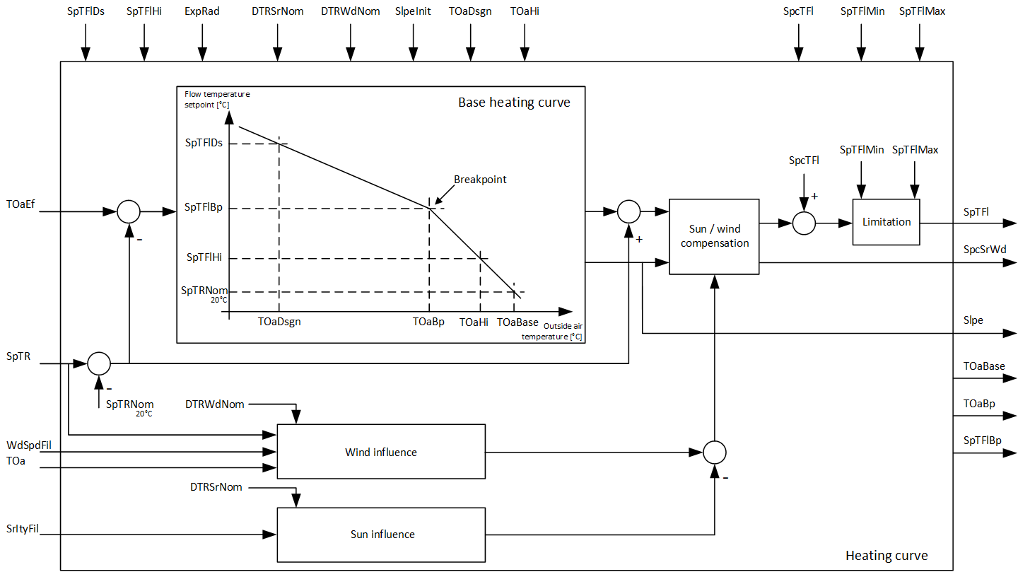
The HCRV (FB412) block calculates the flow temperature setpoint and the average heating curve slope. HCRV SiUn (FB412); HCRV_UsUn (FB791)
Function diagram
The flow temperature setpoint is calculated based on the following:
- Effective outside temperature
- The room setpoint.
- The filtered intensity of solar radiation (solar compensation).
- The filtered wind speed (wind compensation).
- The present outside temperature.
Block HRA (FB113) supplies the default values of the effective outside temperature and the filtered wind speed.
Inputs
Connecting thread | E | Description |
TOaEf | pa | Effective outside temperature Issued by the heating release algorithm HRA (FB113). Average of the present and low-pass filtered outside temperature. The outside temperature filter includes the fact that the room temperature's response to the outside temperature changes is delayed and attenuated. |
TOa | pa | Outside air temperature Must be interconnected only for wind compensation. |
SpTR | pa | Room temperature setpoint To be interconnected only for room temperature controls or pre-control for room heating groups. For these applications, the set heating curve always applies to the nominal room temperature setpoint of 20°C / 68 °F. Other room temperature setpoints must be defined via this input. |
SrItyFil | pa | Solar radiation intensity filtered. To be interconnected only with FILTER (FB127). |
WdSpdFil | pa | Filtered wind speed. To be interconnected only for wind compensation with HRA (FB113) or FILTER (FB127). |
SpcTFl | pa | Setpoint corr.flow temp. Correction of the flow temperature setpoint (e.g. by room controller). |
SpTFlMax | pa | Max.flow temp.setpoint. Maximum flow temperature setpoint. Note: The following influences of the flow temperature setpoint must be considered, i.e. plant protection is limited. |
SpTFlMin | pa | Min.flow temp.setpoint. Minimum flow temperature setpoint. Note: The following influences of the flow temperature setpoint must be considered, i.e. plant protection is limited. |
TOaDsgn | pax | Design outside temperature. Defined as per the planning data of the heating plant. |
SpTFlDs | pa | Flow temperature setpoint for design outside temperature. Defined as per the planning data of the heating plant. |
TOaHi | pax | Outside temperature high. Should be in the upper range of the outside temperatures during the heating period. The entered default value is limited internally so that the contributory point ([TOaHi] / [SpTFlHi]) is always to the right of the design point (TOaDsgn/SpTFlDs). |
SpTFlHi | pa | Flow temperature setpoint for highest outside temperature. Defined as per the planning data of the heating plant. The entered default value is limited internally so that the contributory point ([TOaHi] / [SpTFlHi]) is always to the right below of the design point ([TOaDsgn] / [SpTFlDs]). |
ExpRad | pa | Radiator exponent The higher [ExpRad], the stronger the breakpoint of the heating curve, i.e., the greater the deviation of the heating curve from the straight line. Recommended setting for typical heating systems: Radiators 1.3 |
DTRSrNom | pa | Room temp. increase at nominal solar radiation. Based on nominal conditions (nominal room temperature, design outside air temperature, solar radiation intensity = 0), if the solar radiation intensity increases to a nominal value of 1000 W/m² / 93 W/ft² and if no solar compensation were to take place. If the input [SrltyFil] is interconnected and solar compensation is still not wanted, set [DTRSrNom] to 0. |
DTRWdNom | pa | Room temperature drop at nominal wind speed. Based on nominal conditions (nominal room temperature, design outside air temperature, wind speed 0), if the wind speed increases to a nominal value of 20 m/s / 4000 ft/min and if no wind compensation were to take place. If the input [WdSpdFil] is interconnected and wind compensation is not wanted, set [DTRWdNom] to 0. |
SlpeInit | pa | Slope initialization. Effective only if interconnected to the adaptation block. Without adaptation block [SlpeInit] = 0 (default value). |
Outputs
Connecting thread | E | Description |
SpTFl | a | Flow temperature setpoint Defined by the heating curve. Comprises any corrections to include deviations of the nominal room temperature setpoint and for solar and wind compensation. |
Slpe | a | Slope. Output for use in subsequent blocks (e.g., in room temperature controller with slope-dependent gain). |
SpcSrWd | a | Setpoint correction for solar radiation and wind. |
TOaBp | a | Outside temperature at breakpoint. Graphical output of the heating curve. |
SpTFlBp | a | Flow temperature setpoint at breakpoint. Graphical output of the heating curve. |
TOaBase | a | Base point for outside temperature. Graphical output of the heating curve. |
Input values
Connecting thread | Description | Data type | Default value | E.g. engineering unit or text group | Min. | Max. |
TOaEf | Effective outside temperature | Real | 0.0 | °C | -100.0 | 50.0 |
32.0 | °F | -148.0 | 122.0 | |||
TOa | Outside air temperature | Real | 0.0 | °C | -100.0 | 50.0 |
32.0 | °F | -148.0 | 122.0 | |||
SpTR | Room temperature setpoint | Real | 20.0 | °C | 5.0 | 35.0 |
68.0 | °F | 41.0 | 95.0 | |||
SrItyFil | Sol.radiation intns.fil. | Real | 0.0 | W/m2 | 0.0 | 1000.0 |
0.0 | W/ft2 | 0.0 | 93.0 | |||
WdSpdFil | Filtered wind speed. | Real | 0.0 | m/s | 0.0 | 20.0 |
0.0 | ft/min | 0.0 | 4000.0 | |||
SpcTFl | Setpoint corr.flow temp. | Real | 0.0 | K | -10.0 | 10.0 |
0.0 | °F | -36.0 | 36.0 | |||
SpTFlMax | Max.flow temp.setpoint. | Real | 95.0 | °C | 20.0 | 130.0 |
203.0 | °F | 68.0 | 266.0 | |||
SpTFlMin | Min.flow temp.setpoint. | Real | 20.0 | °C | 10.0 | 65.0 |
68.0 | °F | 50.0 | 149.0 | |||
TOaDsgn | Design outside temperature. | Real | -11.0 | °C | -50.0 | 10.0 |
12.0 | °F | -58.0 | 50.0 | |||
SpTFlDs | FT setp.design OT. | Real | 60.0 | °C | 25.0 | 130.0 |
140.0 | °F | 77.0 | 266.0 | |||
TOaHi | Outside temperature high. | Real | 15.0 | °C | 5.0 | 25.0 |
59.0 | °F | 41.0 | 77.0 | |||
SpTFlHi | Flow temp.setp.high OT. | Real | 30.0 | °C | 20.0 | 65.0 |
86.0 | °F | 68.0 | 149.0 | |||
ExpRad | Radiator exponent | Real | 1.3 | - - - | 1.0 | 1.5 |
DTRSrNom | RT incr.nom.sol.radiation. | Real | 5.0 | K | 0.0 | 15.0 |
9.0 | °F | 0.0 | 27.0 | |||
DTRWdNom | RT decr.nom.wind speed. | Real | 5.0 | K | 0.0 | 10.0 |
9.0 | °F | 0.0 | 18.0 | |||
SlpeInit | Slope initialization. | Real | 0.0 | - - - | 0.0 | 25.0 |
Output values
Connecting thread | Description | Data type | Default value | E.g. engineering unit or text group | Min. | Max. |
SpTFl | Flow temperature setpoint | Real | 20.0 | °C | 0.0 | 130.0 |
68.0 | °F | 32.0 | 266.0 | |||
Slpe | Slope. | Real | 1.0 | - - - | 0.0 | 25.0 |
0.0 | K / °F | -3.403E38 | -3.403E38 | |||
SpcSrWd | Setp.corr.sol.radi.& wind. | Real | 10.0 | °C | -50.0 | 700.0 |
50.0 | °F | -58.0 | 1292.0 | |||
TOaBp | Outs.temp.at breakpoint. | Real | 35.0 | °C | 20.0 | 130.0 |
95.0 | °F | 68.0 | 266.0 | |||
SpTFlBp | FT setpoint at breakpoint. | Real | 20.0 | °C | 5.0 | 700.0 |
68.0 | °F | 41.0 | 1292.0 | |||
TOaBase | Base point for OT. | Real | 20.0 | °C | 0.0 | 130.0 |
Use
The HCRV block calculates the flow temperature setpoint for weather-dependent flow temperature controls.
Note
[SpTRNom] is a constant with a value of 20 °C / 68 °F.
Process response
Standard (see General rules and information).
Troubleshooting
Standard (see General rules and information).