Emergency lamp properties
The DALI device Emergency lamp has the type number 1.
Maintained emergency luminaires
Short designation | Description | Identification in Web interface |
|---|---|---|
Emergency luminaire
| The control gear of a maintained stand-alone emergency luminaire operates the lamp in the emergency mode or the test mode no matter if normal mains is present or not. The control gear does not support switching on/off and dimming using DALI commands. Maintained stand-alone emergency luminaires are always on. | EML-C |
Emerg.luminaire & dimm.lamp
| Maintained dimmable emergency luminaires contain one control gear that always operates the lamp no matter if normal mains is present or not. The control gear operates the lamp in the emergency mode or the test mode and supports switching on/off and dimming using DALI commands. | EML-A |
Emerg.luminaire & swi.lamp
| Maintained switchable emergency luminaires contain one control gear that always operates the lamp no matter if normal mains is present or not. The control gear operates the lamp in the emergency mode or the test mode and supports switching on/off and dimming using DALI commands. | EML-B |



Non-maintained emergency luminaires
Short designation | Description | Identification in Web interface |
|---|---|---|
Emergency luminaire
| The control gear of a non-maintained stand-alone emergency luminaire operates the lamp in the emergency mode or the test mode only if the normal mains fails. The control gear does not support switching on/off and dimming using DALI commands. Non-maintained stand-alone emergency luminaires are only on if the normal mains fails. | EML-D |
Comb.emerg.lum.&dimm.lamp
| Non-maintained dimmable emergency luminaires contain two control gears. | |
| EML-D | |
| G-FL | |
Comb.emerg.lum.&swi.lamp
| Non-maintained switchable emergency luminaires contain two control gears. | |
| EML-D | |
| SWI | |



Properties
The listed properties are displayed in the Hardware and network editor > Inspector window > Properties tab when the DALI device is selected in the Device view tab.
General
Property text | Description | Default value |
|---|---|---|
Template | Template define which template is used. The template stores name, values and used information.
|
|
Name | Name is a text field to enter the name of the device. The name is shown in the device view. | Depends on the selected device. |
Comment | Comment is a text field to enter any helpful information on the device. | Depends on the selected device. |
Short designation | Short designation shows a short description of the device. Read only. | Depends on the selected device. |
Order number | Order number is a text field to enter the order number. | Device type of the selected device. |
Version | Version shows an Internal version of the device. Read only. | V2.0 |
Description | Description shows a short description of the device. Read only. | Depends on the selected device. |
 List of available templates
Device
Property text | Description | Default Value |
|---|---|---|
Short address | Short address shows the address used to communicate point-to-point with one device. Read only. The short address is applied in the installation tool. Range: -1: unconfigured | -1 |
Group address1) | Group address defines the DALI group number. Devices with the same DALI group number are controlled by the same Lighting-Output-Object (LgtAOut). Range: -1: device is not part of a DALI group. 0…15: group addresses | -1 |
Serial number | Serial number shows the serial number of the device. Read only. The serial number is assigned during installation and commissioning. | - |
 0...63
1) This property is not available for devices that are only used for emergency lighting.
Alarming
Property | Description | Default value |
|---|---|---|
Alarming |
|
|
 : Alarming is disabled.
 : Alarming is enabled. An Event Enrollment (EE) object is created.
 Functions
Emergency luminaire
Property text | Description | Default Value |
|---|---|---|
Failure level | Failure level defines the level of light in case of a failure of the DALI communication. Unit: none Range: 0: light is off. 1: light is on. 254: brightest value 255: keeps the current level of light. | 254 |
Power-on level | Power-on level defines the level of light the device goes to after a power-return. The device reacts to DALI commands 0.5 s after power-on. If no command affecting power level is received within 0.6 s after mains power-on, the device will go to Power-on level immediately without fading. Range: 0: light is off. 1: light is on. 254: brightest value 255: keeps the current level of light. | 254 |
Maximum emergency level | Maximum emergency level defines the highest allowed dimming value of the Control Gear in emergency mode. Range: The value is product specific and defined by the manufacturer of the control gear. The control gear will return 255 as unknown, invalid value, if the setting is not supported. | 255 |
Minimum emergency level | Minimum emergency level defines the lowest allowed dimming value of the Control Gear in emergency mode. Range: The value is product specific and defined by the manufacturer of the control gear. The control gear will return 255 as unknown, invalid value, if the setting is not supported. | 255 |
Special parameters: Low dimming limit
Property text | Description | Default Value |
|---|---|---|
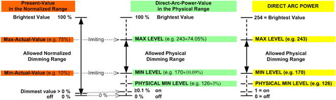
Low dimming limit | Low dimming limit defines to lower limit of the dimming range.
|
|
Switch-on level | Switch-on level defines the level of light for switching on:
See figure Dimming range below. |
|
Fade time configuration | Fade time configuration defines the time to dim to a set level of light.
| 0.7 [s] |
Fade time1) |
|
|
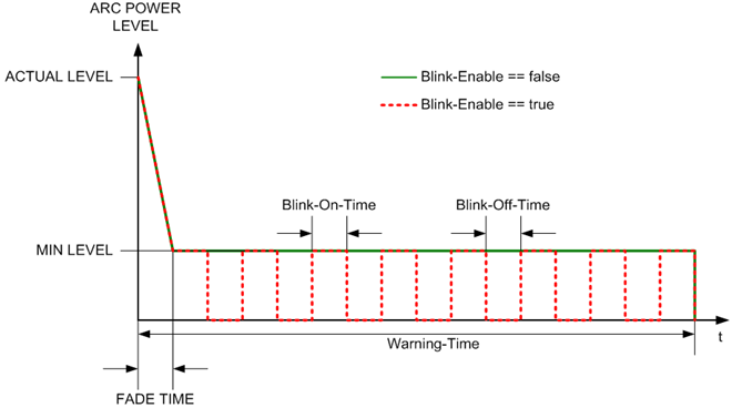
Activate warning1) | Activate warning defines if building users are notified of an upcoming switch-off of the luminaires by dimming-down to minimum level warning.
|
|
Warning time1) | Warning time defines the time during which the warning is performed. Unit: [s] Range: | 10 |
Activate blinking | Activate blinking defines if building users are notified of an upcoming switch-off of the luminaries by blinking on a minimum level.
|
|
Blink-on time | The Blink-off time and the Blink-on time define the blinking frequency for the blink warning function. The Blink-on time defines how long the light will be switched on. See figure Blink enable below. Unit: [0.1 s] Range: 0: the blink warning function is disabled. | 15 |
Blink-off time | The Blink-off time and the Blink-on time define the blinking frequency for the blink warning function. The Blink-off time defines how long the light will be switched off or dimmed to the dimming level defined by Prewarning minimum level. See figure Blink enable below. Unit: [0.1s] Range: 0: the blink warning function is disabled. | 5 |
PrioForcedCtrl2) | PrioForcedCtrl defines the priority for the blink warning function. The blink warning function and autonomous timed-off function are only executed when the present priority > PrioForcedCtrl. Range: | 5 |
DimUpDownTime2) | DimUpDownTime defines the time needed to dim over the entire dimming range from 0% to 100% or from 100% to 0%. Unit: [1/10 s] Range: | 57 |
Prewarning minimum level2) | Prewarning minimum level defines the dimming level for the blink-off time of the blink warning function. Prewarning minimum level is only meaningful if the blink warning function is enabled. Unit: [%] Range: | 0 |
 0 %: To off.
 Minimum: Dim down to minimum level.
1) This property is only supported in Desigo V5.x
2) This property is not supported in Desigo V5.x
Additional properties for combined emergency luminaires
Combined emergency luminaires have an additional function, either the generic fluorescent lamp or a switching function.
Properties for these functions are described in the according topic: