Generic lamp properties
|
|
|
|


Properties
The listed properties are displayed in the Hardware and network editor > Inspector window > Properties tab when the DALI device is selected in the Device view tab.
General
Property text | Description | Default value |
|---|---|---|
Template | Template define which template is used. The template stores name, values and used information.
|
|
Name | Name is a text field to enter the name of the device. The name is shown in the device view. | Depends on the selected device. |
Comment | Comment is a text field to enter any helpful information on the device. | Depends on the selected device. |
Short designation | Short designation shows a short description of the device. Read only. | Depends on the selected device. |
Order number | Order number is a text field to enter the order number. | Device type of the selected device. |
Version | Version shows an Internal version of the device. Read only. | V2.0 |
Description | Description shows a short description of the device. Read only. | Depends on the selected device. |
 List of available templates
Device
Property text | Description | Default Value |
|---|---|---|
Short address | Short address shows the address used to communicate point-to-point with one device. Read only. The short address is applied in the installation tool. Range: -1: unconfigured | -1 |
Group address | Group address defines the DALI group number. Devices with the same DALI group number are controlled by the same Lighting-Output-Object (LgtAOut). Range: -1: device is not part of a DALI group. 0…15: group addresses Note: This property is not applicable to DALI-2 devices. | -1 |
Serial number | Serial number shows the serial number of the device. Read only. The serial number is assigned during installation and commissioning. | - |
 0...63
Alarming
Property | Description | Default value |
|---|---|---|
Alarming |
|
|
 : Alarming is disabled.
 : Alarming is enabled. An Event Enrollment (EE) object is created.
 Functions
Property text | Description | Default Value |
|---|---|---|
Failure level | Failure level defines the level of light in case of a failure of the DALI communication. Unit: none Range: 0: light is off. 1: light is on. 254: brightest value 255: keeps the current level of light. | 254 |
Power-on level | Power-on level defines the level of light the device goes to after a power-return. The device reacts to DALI commands 0.5 s after power-on. If no command affecting power level is received within 0.6 s after mains power-on, the device will go to Power-on level immediately without fading. Range: 0: light is off. 1: light is on. 254: brightest value 255: keeps the current level of light. | 254 |
Special parameters: Low dimming limit
Property text | Description | Default Value |
|---|---|---|
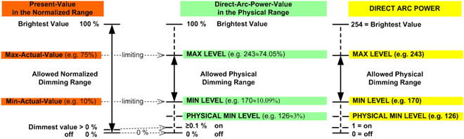
Low dimming limit | Low dimming limit defines to lower limit of the dimming range.
|
|
Switch-on level | Switch-on level defines the level of light for switching on:
See figure Dimming range below. |
|
Fade time configuration | Fade time configuration defines the time to dim to a set level of light.
| 0.7 [s] |
Fade time1) |
|
|
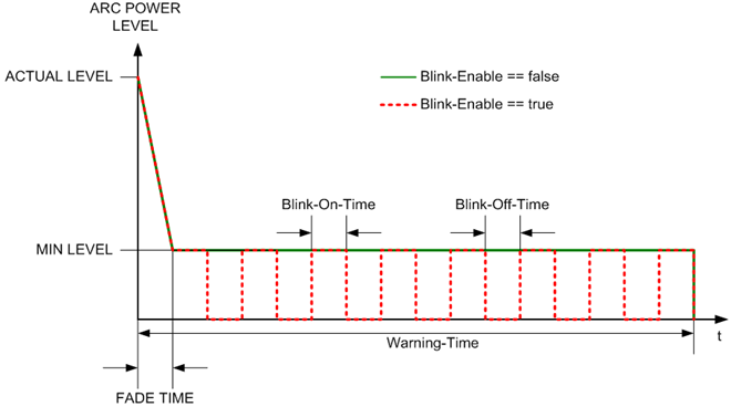
Activate warning1) | Activate warning defines if building users are notified of an upcoming switch-off of the luminaires by dimming-down to minimum level warning.
|
|
Warning time1) | Warning time defines the time during which the warning is performed. Unit: [s] Range: | 10 |
Activate blinking | Activate blinking defines if building users are notified of an upcoming switch-off of the luminaries by blinking on a minimum level.
|
|
Blink-on time | The Blink-off time and the Blink-on time define the blinking frequency for the blink warning function. The Blink-on time defines how long the light will be switched on. See figure Blink enable below. Unit: [0.1 s] Range: 0: the blink warning function is disabled. | 15 |
Blink-off time | The Blink-off time and the Blink-on time define the blinking frequency for the blink warning function. The Blink-off time defines how long the light will be switched off or dimmed to the dimming level defined by Prewarning minimum level. See figure Blink enable below. Unit: [0.1s] Range: 0: the blink warning function is disabled. | 5 |
PrioForcedCtrl2) | PrioForcedCtrl defines the priority for the blink warning function. The blink warning function and autonomous timed-off function are only executed when the present priority > PrioForcedCtrl. Range: | 5 |
DimUpDownTime2) | DimUpDownTime defines the time needed to dim over the entire dimming range from 0% to 100% or from 100% to 0%. Unit: [1/10 s] Range: | 57 |
Prewarning minimum level2) | Prewarning minimum level defines the dimming level for the blink-off time of the blink warning function. Prewarning minimum level is only meaningful if the blink warning function is enabled. Unit: [%] Range: | 0 |
 0 %: To off.
 Minimum: Dim down to minimum level.
1) This property is only supported in Desigo V5.x
2) This property is not supported in Desigo V5.x