Extract air VAV box, pressure sensor, flow conversion (VavEx13)
| This application function operates a damper, using internal air volume flow controller to drive the measured air volume flow to an air volume flow setpoint. To calculate air volume flow, this AF uses an OEM box flow coefficient (K-factor) and input from a differential pressure sensor. The air volume flow setpoint is calculated based on request for extract flow, relative to the volume of air flowing through the supply terminal following the principle of «extract tracks supply». |
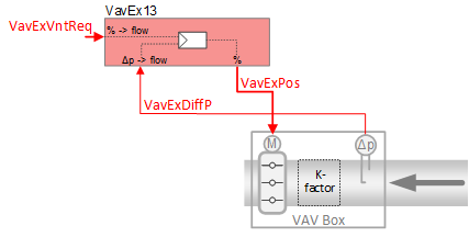
Required elements and how to configure them:
Element | I/O | Signal type |
|---|---|---|
VavExPos "Extract air VAV position" | On-board output, Extract air VAV position | 0…10V or 3-position |
or KNX PL-Link device, Extract air VAV | Position control | |
VavExDiffP "Extract air VAV differential pressure" | On-board input, Extract air VAV differential pressure | 0…10V |
Function
The figure below shows BACnet objects associated with this application function. Primary signal flow is summarized as follows:
VAV extract ventilation request (VavExVntReq) is received and processed into the output signal for VAV extract damper position (VavExPos).
Basic function: Accept the extract ventilation request signal from associated room controller and map it to the extract air volume flow setpoint; Compare setpoint to air volume flow in extract terminal box; Pass result through a device mode logic switch prior to outputting as a command to the object that controls the device.
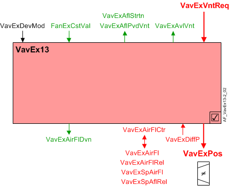
| Command or request (or related) |
| Notification of condition or status, or availability |
| Device mode |


Air flow controller: The PID air flow controller (VavExAirFlCtr) compares the current extract air flow to the current extract air flow setpoint (VavExSpAirFl) and adjusts VavExPos as necessary to keep the box flow at setpoint.
VavExSpAirFl drives the air flow controller / actuator either through a 0-10V DC signal or a networked I/O to a field device on PL-Link.
Saturation signal: The saturation signal (VavExAflStrtn) is a binary object that is True ("Starved") when the air flow control loop cannot get enough air to reach setpoint for a time exceeding a built-in time delay.
Note
VavExAflStrtn is always off if parameter EnStrtnCal = 0 (No). This allows the user to exclude a particular terminal from the saturation pressure reset system.
Air flow deviation signal: The extract air flow deviation (VavExAirFlDvn) signal (in percent) is used for fan speed (static pressure) reset strategies at the air handling unit. It is obtained by measuring the air flow from the extract duct and comparing it to the air flow setpoint.
VavExAirFlDvn = VavExSpAflRel minus VavExAirFlRel
VavExAirFlDvn will = 0 in case of invalid condition(s).
Available status: When the VAV extract damper is available for extract air ventilation, the binary output signal that indicates availability (VavExVntReq) will be "Yes" (available).
For available status to be "Yes", device mode must equal "Control mode" (modulation).
The output signal VavExAflPvdVnt is the amount of air flow available for extract air ventilation. When VavExAvlVnt is True, a maximum value (VavExAflMaxVnt) is transferred to VavExAflPvdVnt.
VavExAflPvdVnt (VAV extract air flow provided for ventilation) is the sum of maximal flow (in engineering units) from the extract VAV boxes. These values are set in each extract VAV for the maximum flow in the segment.
Device mode: The input signal for device mode is a multistate value.
VavExDevMod supports the following states:
- Off
- Control mode (modulation)
- Max.air vol.flow
- Min.air vol.flow
- Smoke ctrl.air flow setp (manually entered damper setpoint value for smoke control)
Device mode: The input signal for device mode is a multistate value.
VavExDevMod supports the following states:
- Off
- Control mode (modulation)
- Max.air vol.flow
- Min.air vol.flow
- Smoke ctrl.air flow setp (manually entered damper setpoint value for smoke control)
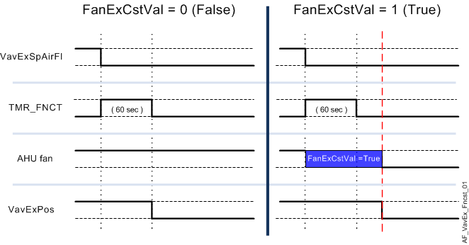
Fan coasting feature: The fan coasting feature prevents premature closing of the extract damper while the AHU fan is coasting down. This might occur during a switch between operating modes (for example, switching from Comfort to Economy).
The fan coasting feature is active when:
- The extract air damper is the only extract damper that is open – all other extract air dampers are closed.
- The AHU fan has been turned off and is coasting down.
- The air flow setpoint signal (VavExSpAirFl) while on its way to zero, falls below the air flow demand hysteresis setting (HysAirFlDmd).
When these conditions are true, the boolean extract fan coasting signal (FanExCstVal) will equal 1 (True) and the damper is reset to its last (previous) operating position / value. This keeps the damper open while the fan coasts down to prevent extract duct over-pressure.
In addition to the fan coasting signal freezing the damper in place, an internal timer function was activated when (VavExSpAirFl) initially dropped below (HysAirFlDmd). The fan coasting signal and the timer (60 seconds) must both finish (return to False) before the extract damper can close. See the figure below.
Note
The internal timer operates independently and regardless of VavExSpAirFl. Once the timer is activated, the extract damper is frozen in place until the counter reaches zero, after which the damper may close.
Configuration
 Objects
Description | Object | Type | Default value |
|---|---|---|---|
Extract air VAV box coefficient | VavExBoxCoef | ACnfVal | 150.0 [m3/h/SqrtPa] |
Extract air VAV initial flow coefficient | VavExFlCoefIni | ACnfVal |
|
Air flow settings | |||
Extract air VAV smoke control air volume flow setpoint | VavExSpAflSmk | ACnfVal | 50.0 [m3/h] |
Extract air VAV maximum air volume flow for ventilation | VavExAflMaxVnt | ACnfVal | 100.0 [m3/h] |
Extract air VAV minimum air volume flow for ventilation | VavExAflMinVnt | ACnfVal | 0.0 [m3/h] |
 Parameters
Description | Parameter | Default value |
|---|---|---|
Nominal air volume flow | AirFlNom | 100.0 [m3/h] |
Differential pressure | ||
Switch-on point for differential pressure | SwiOnPtDiffP | 0.2 [Pa] |
Hysteresis for differential pressure | HysDiffP | 0.1 [Pa] |
Deviation calculation | ||
Enable deviation calculation 0:No | EnDvnCal | 1:Yes |
Saturation calculation | ||
Enable saturation calculation Saturation signal calculation logic: (VavExPos > StrtnLvl) and (VavExAirFlDvn> AirFlErLm). This feature is used for AHU fan static pressure reset. See also Saturation signal section. 0:No | EnStrtnCal | 1:Yes |
Saturation level | StrtnLvl | 90 [%] |
Air volume flow error limit | AirFlErLm | 0 [%] |
Switch-on delay saturation | DlyOnStrtn | 60 [s] |
Airflow demand | ||
Switch-on point for air flow demand | SwiOnAirFlDmd | 4 [%] |
Hysteresis for air flow demand | HysAirFlDmd | 2 [%] |
Enable monitoring for missing air volume flow 0:No | EnMonNoAirFl | 0:No |
Internal settings – do not change | ||
Pressure unit | PUnit | [Pa] |
Air volume flow unit | AirFlUnit | [m3/h] |
Interface
Interface | Description | Type | Ref. | Owned by |
|---|---|---|---|---|
VavExPos | Extract air VAV position | AO | ◉ | Room segment / Device |
VavExDiffP | Extract air VAV differential pressure | AI | ◉ | Room segment / Device |
VavExSpAirFl | Extract air VAV setpoint for air volume flow | APrcVal | ● | - |
TrndVavExSpAfl | Trend for extract air VAV setpoint for air volume flow | FtrSel | ● | - |
VavExSpAflRel | Extract air VAV setpoint for relative air volume flow | ACalcVal | ● | - |
VavExAirFl | Extract air VAV air volume flow | ACalcVal | ● | - |
TrndVavExAirFl | Trend for extract air VAV air volume flow | FtrSel | ● | - |
VavExAirFlRel | Extract air VAV relative air volume flow | ACalcVal | ● | - |
VavExAirFlDvn | Extract air VAV air volume flow deviation | ACalcVal | ● | - |
VavExAflStrtn | Extract air VAV air volume flow saturation 0:Satisfied | BCalcVal | ● | - |
VavExDevMod | Extract air VAV device mode 1:Off | MPrcVal | ● | - |
VavExAirFlCtr | Extract air VAV air flow controller | Controller | ● | - |
VavExVntReq | Extract air VAV ventilation request | ACalcVal | ● | - |
VavExAvlVnt | Extract air VAV available for ventilation 0:No | BCalcVal | ● | - |
FanExCstVal | Coasting value of extract air fan 0:Off | BCalcVal | ● | - |
VavExAflPvdVnt | Extract air VAV provided air volume flow for ventilation | ACalcVal | ● | - |
VavExSplyAir | Extract air VAV supply chain for air | GrpMbr | ● | - |
VavExSpAflSmk | Extract air VAV smoke control air volume flow setpoint | ACnfVal | ● | - |
VavExBoxCoef | Extract air VAV box coefficient | ACnfVal | ● | - |
VavExAflMaxVnt | Extract air VAV maximum air volume flow for ventilation | ACnfVal | ● | - |
VavExAflMinVnt | Extract air VAV minimum air volume flow for ventilation | ACnfVal | ● | - |
Engineering and commissioning
Check for correct damper actuator installation. Actuator mis-wiring or improper installation is a major cause of common problems.
The relative air flow (VavExAirFlRel) is normalized as a percentage (0 - 100%) of VavExAirFl based on the nominal (rated) value for the box air flow (AirFlNom).