VAV ventilation control (VavVntCtl11)
Overview
The application function "VAV ventilation control 11" (VavVntCtl11) collaborates with VAV supply air terminal boxes for ventilation and/or room air quality control.
Function
Different modes are available for ventilation control; the behavior is selectable by parameter.
Ventilation mode
The ventilation mode can be set per room operating mode to:
- Off
- Minimum (Constant air flow)
- Dcv (Demand controlled ventilation) 1)
- Dcv & Min (Demand controlled ventilation with a minimum air flow limit) 1)
1) Air quality sensor required in the room.
The table shows factory default settings for min vent and air quality parameters:
Plant mode | Ventilation mode | Sp air quality | AirFlMin |
|---|---|---|---|
1 Off | Off |
|
|
2 Protection* | Off | 1500 | 50 |
3 Economy* | Off | 1500 | 50 |
4 Pre-Comfort* | Dcv | 1100 | 50 |
5 Comfort* | Min & Dcv | 900 | 50 |
6 Warm-up | Off |
|
|
7 Cool down | Off |
|
|
8 Room low temperature protection | Off |
|
|
9 <not used> |
|
|
|
10 Free cooling | Depends on ROpMod | Depends on ROpMod | Depends on ROpMod |
11 Night cooling | Off |
|
|
12 Rapid ventilation | s/a Comfort | s/a Comfort | s/a Comfort |
13 <not used> |
|
|
|
14 Emergency off | Off |
|
|
15 Max.supply air vol.flow only (positive pressure) | Off |
|
|
16 Max.extract air vol.flow only (negative pressure) | Off |
|
|
17 Purge | Off |
|
|
*For these modes the parameters can be individually adjusted.
NOTICE

Minimum ventilation air flow settings in VavVntCtl11
VAV PID controller is not enabled unless ventilation flow setpoint is above 7% of max air flow setting (hardcoded).
- If minimum ventilation is required, set minimum ventilation air flow setting(s) >7% of the largest maximum air flow setpoint.
Minimum ventilation setup
Minimum ventilation air flow settings should be >7% of the largest maximum air flow setpoint value (typically cooling flow maximum, VavSuAirFlMaxC located in the segment AF VavSu.xx). The nominal air volume flow parameter (AirFlNom, also located in the segment AF VavSu.xx) should be set equal to this largest maximum air flow setpoint value.
In the following examples, cooling flow maximum (VavSuAirFlMaxC) is assumed to be the largest maximum air flow setpoint.
Example 1
In this example, assume AirFlNom and VavSuAirFlMaxC have both been set to 1000 m3/h, and the minimum ventilation setpoint object (VavSuAflMinVnt, located in the segment AF VavSu.xx) has been set tozero. Setting VavSuAflMinVnt in the segment AF to zero allows the min vent parameter settings in this AF (VAV ventilation control, VavVntCtl11) to vary per the room operating mode (Comfort, Pre-Comfort, Economy, Protection). See table.
Room mode ventilation flow value | Ventilation mode setting | Result |
|---|---|---|
AirFlMinRCmf = 100 m3/h | CmfCnf = Min vent & DCV | In Comfort, ventilation flow will have a low limit of 100 m3/h and may rise with air quality demand (DCV). |
AirFlMinRPcf = 80 m3/h | PcfCnf = Min vent | In Pre-Comfort, ventilation flow = 80 m3/h. |
AirFlMinREco = 60 m3/h | EcoCnf = Min vent | In Economy, ventilation flow will be zero, because AirFlMinREco was incorrectly set to 60 m3/h which is less than 7% of AirFlNom (AirFlNom was set to 1000 m3/h). |
AirFlMinRPrt = 80 m3/h | PrtCnf = Off | In Protection, the mode setting (PrtCnf) has been set to Off. When a ventilation mode setting = Off, ventilation flow for that room mode will be zero regardless of the parameter flow value (in this case, AirFlMinRPrt) or the value of VavSuAflMinVnt. |
Example 2
In this example, assume AirFlNom and VavSuAirFlMaxC have both been set to 1000 m3/h, and the minimum ventilation setpoint object (VavSuAflMinVnt) located in the segment AF VavSu.xx has been set to 100 m3/h.
Room mode ventilation flow setting | Ventilation mode setting | Result |
|---|---|---|
AirFlMinRCmf = 125 m3/h | CmfCnf = Min vent | In Comfort, ventilation flow will be 125 m3/h. |
AirFlMinRPcf = 90 m3/h | PcfCnf = Min vent | In Pre-Comfort, ventilation flow = 100 m3/h (not 90) because VavSuAflMinVnt was set to 100, which is larger than 90; (90 and 100 are each >7% AirFlNom, so they are both valid (usable) values; when valid settings conflict, the larger value wins). |
AirFlMinREco = 50 m3/h | EcoCnf = Min vent | In Economy, ventilation flow will = 100 m3/h because VavSuAflMinVnt was set to 100. |
AirFlMinRPrt = 50 m3/h | PrtCnf = Off | In Protection, the mode setting (PrtCnf) has been set to Off. When a ventilation mode setting = Off, ventilation flow for that room mode will be zero regardless of the parameter flow value (in this case, AirFlMinRPrt) or the value of VavSuAflMinVnt. |
Demand Controlled Ventilation with Proportional Control - Configuration
Typical DCV (Demand control ventilation) uses only the "P" of the PID control loop. (PID: Proportional gain; Integral; Derivative).
DCV also uses outside air to maintain a ppm differential between good/bad indoor air quality.
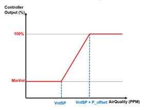
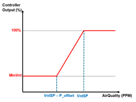
When indoor air quality is at or above the hi limit ppm setpoint, PID loop output should be 100%. This control behavior can be configured by adjusting properties of the Ventilation controller object (VntCtr, Ventilation controller).
Set VntCtr properties as follows:
Integral:0
Derivative:0
Controller Output for Offset:100
The Controller Output for Offset parameter determines PID output when the measured value is at setpoint. Reference the specifications document and set accordingly.
Examples of Minimum VS Maximum Ventilation at Setpoint | |
The left graph shows an example of the behavior of the controller at default settings. The graph on the right shows an example the behavior of the controller after the VntCtr properties have been configured using the settings listed previously in the DCV with Proportional Control section. | |
Minimum Ventilation at Setpoint (default) | Maximum Ventilation at Setpoint |
|
|
Periodic air flush
Parameters are available to configure periodic cycling of ventilation air flow. Ventilation can be enabled for minimum air flow at regular intervals, for the length of time in TiOnDutyCyc. See figure.
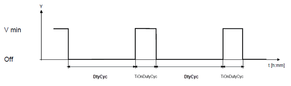
The length of the duty cycle off interval can be configured for each operating mode (DutyCycCmf, DutyCycPcf, DutyCycEco, DutyCycPrt). A duty cycle of 0min (default) means the feature is disabled.
Note
If the room temperature is measured with an extract air temperature sensor, air must flow to ensure the effective room temperature is measured correctly. In this case, periodic air flush can be used to provide air flow at regular intervals.
Exception handling
For air quality control, the ventilation mode must be set to Dcv or Min & Dcv, VavSuAvlVnt must be Yes and the air quality sensor must be Valid. If the sensor is failed or absent, then the ventilation mode cannot be Dcv or Min & Dcv; in this case VavSuVntReq is set to Min.
Configuration
 Objects
Description | Object | Type | Default value |
|---|---|---|---|
Setpoint room air quality for comfort | SpAQualRCmf | ACnfVal | 900 [ppm] |
Setpoint room air quality for pre-comfort | SpAQualRPcf | ACnfVal | 1100 [ppm] |
Setpoint room air quality for economy | SpAQualREco | ACnfVal | 1500 [ppm] |
Setpoint room air quality for protection | SpAQualRPrt | ACnfVal | 1500 [ppm] |
 Parameters
Description | Parameter | Default value |
|---|---|---|
Comfort configuration 1:Off | CmfCnf | 4:Minimum ventilation & Demand-controlled ventilation |
Pre-Comfort configuration Enumeration see CmfCnf | PcfCnf | 3:Demand-controled ventilation |
Economy configuration Enumeration see CmfCnf | EcoCnf | 2:Minimum ventilation |
Protection configuration Enumeration see CmfCnf | PrtCnf | 2:Minimum ventilation |
Minimum room air volume flow for comfort | AirFlMinRCmf | 50 [m3/h] |
Minimum room air volume flow for pre-comfort | AirFlMinRPcf | 50 [m3/h] |
Minimum room air volume flow for economy | AirFlMinREco | 50 [m3/h] |
Minimum room air volume flow for protection | AirFlMinRPrt | 50 [m3/h] |
Air volume flow unit | AirFlUnit | [m3/h] |
Duty cycling in comfort | DutyCycCmf | 0 [min] |
Duty cycling in pre-comfort | DutyCycPcf | 0 [min] |
Duty cycling in economy | DutyCycEco | 0 [min] |
Duty cycling in protection | DutyCycPrt | 0 [min] |
Switch-on time duty cycling | TiOnDutyCyc | 6 [min] |
Interface
Interface | Description | Type | Ref. | Owned by |
|---|---|---|---|---|
PrSpVnt | Present ventilation setpoint | APrcVal | ● | - |
VntCtr | Ventilation controller | Controller | ● | - |
RCtl | Room control | GrpMaster | ◉ | Room |
SpAQualRCmf | Setpoint room air quality for comfort | ACnfVal | ● | - |
SpAQualRPcf | Setpoint room air quality for pre-comfort | ACnfVal | ● | - |
SpAQualREco | Setpoint room air quality for economy | ACnfVal | ● | - |
SpAQualRPrt | Setpoint room air quality for protection | ACnfVal | ● | - |
Engineering and commissioning
NOTICE
Minimum ventilation air flow settings in VavVntCtl11
VAV PID controller is not enabled unless ventilation flow setpoint is above 7% of max air flow setting (hardcoded).
- If minimum ventilation is required, set minimum ventilation air flow setting(s) >7% of the largest maximum air flow setpoint.