CTR: Controller
Function block description
The CTR (FB300) block is a universal PID controller (P, PI, PD, or PID), with external tracking. It supplies a modulating manipulated variable. CTR_SiUn (FB300), CTR_UsUn (FB349)
Block CTR also helps create the sequence controller and the sequence cascade controller.
- Sequence controller: One CTR per sequence controller element; possibly one SEQLINK block.
- Sequence cascade controller: One CTR per sequence controller element; additional CAS_CTR and possibly one SEQLINK block.
The control response of the sequence controller either differs for each sequence controller element or is the same for all sequence controller elements. CTR_SiUn (FB300), CTR_UsUn (FB349)
The function block CTR can be used as:
- universal P(I)(D) controller,
- universal PI(D) controller with tracking,
- one specific sequence control element within a sequence control logic,
- manager or subordinate controller within a cascade control logic.
It can be used to control variables such as temperature, pressure or humidity.
Functionality of P, PI, PD, PID controllers
The following functionalities are integrated in the function block:
- P, PI, PD, PID, 2-point control or staged control configurable, see table below.
- Gain, integral action time and derivative action time separately parametrizable
- Range of manipulated variable tunable by minimum and maximum control output
- Inversion of manipulated variable configurable
- Control gain factor linkable (for gain adaptation)
- Tunable neutral zone for control error
- Bias (for P and PD controller) parametrizable
- Rise time (for 0 – 100%) and fall time (for 100 – 0%) of the manipulated variable settable
- Control action type configurable (direct/reverse)
| CtrTyp | ||
PID | Staged | ||
| Continuous | PID control (default) Control parameters used: Irrelevant control parameters: | Staged control Control parameters used: NumSts, HysSwiOn, HysSwiOff, SwiDly Irrelevant control parameters: |
2-position | Forced 2-position control Control parameters used: Irrelevant control parameters: | ||

PID controller – stand alone case
When setting the control type [CtrTyp] to PID and the control mode [CtrMod] to Continuous and the controller gain [Gain] > 0, CTR acts as a P(I)(D) controller.
The PID controller has three main parameters to specify the control behavior:
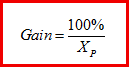
- Controller gain [Gain]
- Integral action time [Tn]
- Derivative action time [Tv]
Optionally, the controller gain can be corrected by the linkable FB variable gain factor [GainFac]. Such a correction or gain scheduling may be helpful for controlling mixed air dampers in air handling units since the control gain depends on measured temperatures.
Other control parameters for the PID controller and their effect are described in various sections below.
Controller output range [YctrMin, YctrMax]
The range of the control output [Yctr] is specified by [YctrMin] and [YctrMax], see figure below. These limits are not valid when the controller is set out of service by [OoServ] = TRUE.

Note: Output limits [YctrMin] > [YctrMax]
If [YctrMin] is greater than [YctrMax], the control output range is set to the single value [YctrMax], i.e. [Yctr] = min{[YctrMin],[YctrMax]}. Therefore, a limiting controller acting on [YctrMax] will be able to force the control output lower than [YctrMin]. On the other hand, a limiting controller acting on [YctrMin] may only increase the control output to [YctrMax].
Controller acting type [Actg]
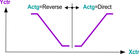
The controller acting type [Actg] determines the relationship between the manipulated variable [Yctr] and the control variable [Xctr], see following figure.
Direct acting: If the actual value [Xctr] increases, the controller output value [Yctr] increases, e.g. cooling, dehumidifying.
Indirect acting: If the actual value [Xctr] increases, the controller output value [Yctr] decreases, e.g. heating, humidifying.
Notes on the inversion of the controller output:
The inversion of the controller output [Yctr] can also be done by using the parameter [Inv]. This may be necessary for sequence control.
Neutral zone [Nz]
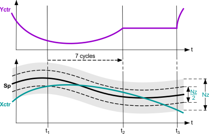
The neutral zone [Nz] is an insensitivity range around the setpoint. If the distance between the setpoint [Sp] and the control variable [Xctr] is smaller than ¼ of the neutral zone for 7 controller cycles, the control output [Yctr] is freezed. Control action is resumed when the distance between the setpoint [Sp] and the control variable [Xctr] is greater than ½ of the neutral zone, see figure below.
Controller output offset [YctrOfs]
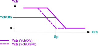
If the controller is parametrized as P or PD controller, a bias or offset [YctrOfs] can be specified. The controller output will be [YctrOfs] if there is no control error (and the controller is switched on), see figure below. The controller output offset [YctrOfs] is also used as an integrator start value in case the controller is parametrized as PI or PID controller: As soon as the controller is switched on and starts controlling, the controller integrator value is set to [YctrOfs].
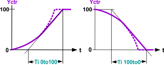
Controller output rise time [Ti0to100] and fall time [Ti100to0]
[Ti0to100], [Ti100to0] limit the maximum signal increase or signal decrease of the manipulated variable [Yctr], see figure below.
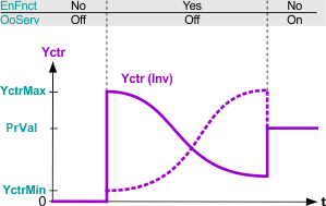
Inverse [Inv]
The inversion of the controller output [Yctr] is essentially calculated according to:
[Yctr]Inv = 100% – [Yctr]NotInv
The controller output limits [YctrMin] und [YctrMax] as well as the controller output rise time [Ti0to100] and fall time [Ti100to0] are (for [Inv] = TRUE) related to the inverted controller output. If the controller is switched of ([EnFnct] = FALSE and [OoServ] = FALSE), the controller output [Yctr] is set to 0% also for the inverted controller, see figure below.
Control variable tracking [EnTrack]/[Track]
Returning the effective manipulated variable to the input [Track] improves the control quality of the PI or PID controller (e.g. anti windup). This is called external control variable tracking.
If [EnTrack] = FALSE, tracking is disabled and [Track] is not processed as a tracking signal.
If [EnTrack] = TRUE, tracking is enabled and [Track] is processed as a tracking signal.
Example: If a controller acts directly on the actuating device (e.g., minim or maximum selection), the positioning signal of the controller does not influence the control path. Returning the effective positioning signal to the tracking input keeps the controller on the present values and guarantees continued, modulating control when the controller can no longer intervenes.
Note: If external tracking is set for the controller element of a sequence, it must be ensured that the set limit values [YctrMin] and [YctrMax] can be reached. Else, the sequence controller can switch to the next sequence controller element only in the event of a high control error. As an alternative to external tracking, the limit values [YctrMin] and [YctrMax] can be influenced directly in the case of limitation applications.
Control algorithm
The P(I)(D) control algorithm implemented in the function block CTR complies 100% with the control standard.
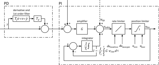
Above: Continuous time block diagram of the PID control algorithm without external tracking (in case of a P or PD controller, the control output offset uOfs is used instead of the integrator value)
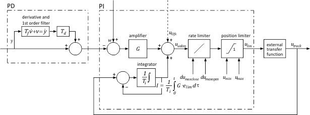
Above: Continuous time block diagram of the PID control algorithm with external tracking
Staged control – stand alone case
When setting the control type [CtrTyp] to Staged Control and the control mode [CtrMod] to Continuous, CTR acts as a staged controller with [NumSts] stages. Setting [CtrMod] to 2-position forces the function block CTR to have a 2-position control regardless of the [CtrTyp] setting, see table on «Control operation modes of FB CTR» earlier in this document.
2-position control
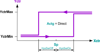
When setting the control mode [CtrMod] to 2-position control, the function block CTR acts as a 2-position controller. Alternatively, a 2-position control behavior can be achieved when setting [Gain] to zero (this applies independently of the setting [CtrTyp], i.e. for PID and for staged control). The switch points are specified by the hysteresis [HysSwiOn] and [HysSwiOff] and the acting type [Actg], see the figure below for direct acting 2-position control.
In order for the controller to switch, the control variable has to exceed the according switch point and the last switching action occurred at least one switch delay time [SwiDly] earlier.
Staged control
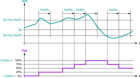
When the absolute control error |[Sp]-[Xctr]| is greater than the switch hysteresis, then the controller increments/decrements the output – except if the last stage switching occurred more recent than the switch delay [SwiDly]. No stage switching will be performed as long as the last stage switch action is more recent than the switch delay, see figure below. There is no minimal time duration criterion for the absolute control error in order to perform a stage switch.
For staged control, the control output [Yctr] will be set in stages of the size 100%/[NumSts] (there is no stage output in the integer format).
Example: If [YctrMin] = 0% and [YctrMax] = 100% and [NumSts] = 4, the control output [Yctr] will be be one of 0%, 25% 50% 75% or 100%, see example in the figure below.
The control output limits [YctrMin] and [YctrMax] can be used to limit the minimum and maximum stage. If the provided values do not correspond exactly to a stage value in percent, the function does round to the nearest stage.
Example: If [NumSts] = 4 and [YctrMin] = 20%, [YctrMin] will be rounded to 25% and the minimal stage used is 1.
The controller offset [YctrOfs] is not used to initialize the staged controller. Also the tracking input Track is not processed by the staged controller.
Changing the control operation type
Changing between integrative and non-integrative control
If a PI(D) controller is changed to a non-integrative controller by setting [Tn] to zero, the integrator value of the controller is set to zero.
If a non-integrative controller (P, PD, staged or 2-position controller) is changed to a PI(D) controller, the existing integrator value of the controller is taken over and limited to the range [YctrMin, YctrMax].
Changing between PID and staged control
If a PI(D) controller is changed to a staged controller, the actual control output [Yctr] is immediately rounded to the nearest stage output. E.g. if [NumSts] = 4, a value of [Yctr] = 69.3% is rounded to [Yctr] = 75%. After that, the staged control algorithm is performed.
For a 2-position or staged controller with integral action time [Tn] > 0, the integrator value is determined by internal tracking of the control output, see Figure 2 7. This is only relevant when the 2-position or staged controller is changed to a PI(D) controller: If a 2-position or staged controller is changed to a PI(D) controller, the tracked integrator value is used.
This procedure typically is beneficial when smooth transition is required, e.g. for the transition between 2-position control for moring warm-up (optimum start control) and PI(D) control for comfort.
Changing between disabled and enabled control
If a controller is disabled ([EnFnct] = FALSE, [OoServ] = FALSE), the control output [Yctr] is set to 0%, independent of [Inv] and other controller settings.
If a PI(D) controller is enabled, the integrator value starts integrating from [YctrOfs]. The control output [Yctr] starts from 0% or [YctrMin] (if [YctrMin] > 0%) or [YctrMax] (if [YctrMax < 0%) respecting the maximul rise and fall times [Ti0to100] and [Ti100to0].
If a staged controller is enabled, the control output [Yctr] starts from 0% if 0% is within the range [YctrMin, YctrMax]. Otherwise, [Yctr] starts bounded within that interval. E.g. [YctrMin] = 15%, [YctrMax] = 70%, [NumSts] = 4, the control output [Yctr] starts at 25% ([YctrMin] rounded).
Changing between out of service and PID or staged control
If a controller is set out of service, the control output [Yctr] is set to the default value [DefVal].
If a PI(D) controller is changed from out of service to “in service”, the integrator value starts integrating from [DefVal].
If a staged controller is changed from out of service to “in service”, the control output [Yctr] is immediately rounded to the nearest stage output (from [DefVal]). E.g. if [NumSts] = 4, a value of [Yctr] = [DefVal] = 69.3% is rounded to [Yctr] = 75%. After that, the staged control algorithm is performed.
PID and staged controller – sequence control case
A sequence controller is used if several aggregates are used to control a controlled value in accordance with the predefined control sequence. The sequence controller switches the individual sequence controller elements according to the control sequences and coordinates control for the individual controller elements in an interrelated control behavior across all sequence controller elements or aggregates.
Sequence controllers primarily are used in air conditioning to control temperature and humidity. However, there is no reason why not to use a sequence controller also for appropriate control problems in other applications.
Building up a sequence controller
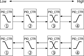
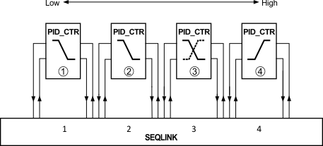
A sequence controller is composed of several sequence elements whereas all sequence elements are instances of the function block CTR. The interconnection of the sequence elements can be done directly or via the sequence linker function block SEQLINK (see figures below).
Communication signals between sequence elements
The sequence elements communicate with each other by the information channels [ToLower] > [FmHigher] and [ToHigher] > [FmLower]. The following information is exchanged by this communication:
Pin | Message | |
[.CtlMod] | Control mode | |
(1) Nil | Not connected (default value). | |
(2) Act | Control active. | |
(3) Off | Control switched off. | |
(4) On | Control switched on. | |
[.Crdn] | Coordination information | |
(1) Nil | Not connected (default value). | |
(2) Low | Control active. | |
(3) ErrLow | Error of coordination of sequence. | |
(4) High | Control output maximum edge. | |
| (5) ErrHigh | Reserve, not yet used. |
[.Ctkn] | Control token information | |
(1) Nil | Not connected (default value). | |
(2) Low | Controlling element is lower or passed lower. | |
(3) Act | Controller is acting. | |
(4) High | Controlling element is higher or passed higher. | |
[.IsInt] | Integrator information | |
(1) TRUE | Not connected (default value). | |
(2) FALSE | Control active. | |
[.DeltaE] | Error covered by proportional controller part information. | |
(1) Real value. | ||
Acting types of sequence control elements
As a rule, the sequence controller consists of individual CTR blocks. Each CTR acts as a sequence control element for an aggregate. The interconnection sequence of the CTR blocks (from low to high) corresponds to the order of the control sequences (1 ... n) of the sequence controller. The planned operating range (e.g. heating) and the switching sequence must be considered accordingly when interconnecting the CTR elements.
Example sequence control with four elements (see figure below): 1 = Reheater (lowest element), 2 = Preheater, 3 = Air dampers, 4 = Cooler (highest element).
With increasing heat demand, heating is provided in the following order: 3 > 2 > 1.
With increasing cold demand, cooling is provided by element 4 (> 5 … if existing).
The lowest sequence control element corresponds to control sequence 1, the highest to control sequence n. The lowest sequence control element controls an aggregate using reverse action (if available). The highest sequence control element controls an aggregate using direct action (if available).
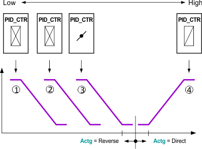
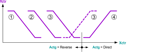
The operation of the controlled aggregate (e.g. heating, cooling) determines the direction of control action [Actg] for a sequence control element. If the acting type of an aggregate changes during operation, such a change has also to be set for the corresponding sequence control element: See figure below for a changing acting type of sequence control element 3. If the controlled aggregate demands an inverted signal, inversion [Inv] of the controller output helps solve this problem.
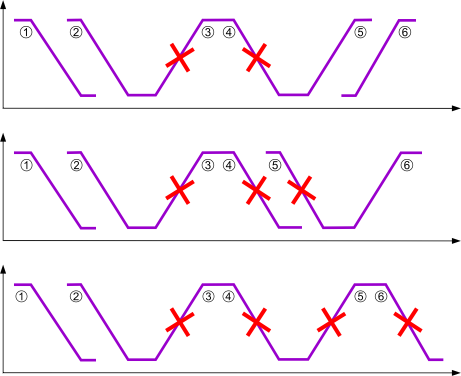
Within a control sequence, the acting type [Actg] from the lowest to the highest sequence control element can be changed only once and only from reverse to direct acting. If this requirement is not met, i.e. if the control action is parameterized incorrectly, faulty control sequence elements are deactivated and the next valid control sequence is released. The incorrectly parameterized sequence controller elements set [ErSta] = Yes. See figure below for examples of faulty configurations.
Faulty control sequence elements will output information on the fault via token state [TknSta]. Direct acting elements will output [TknSta] = Hel_CSeq (cooling element in heating sequence), reverse acting elements will output [TknSta] = Cel_HSeq (heating element in cooling sequence).
Setpoints of sequence control elements
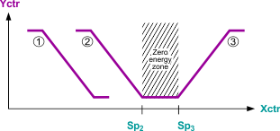
In a sequence controller, the setpoints [Sp] of the sequence control elements (1 ... n) must increase monotonously:
[Sp]1 ≤ [Sp]2 ≤ [Sp]3 ≤ ... ≤ [Sp]n
Modulating control on transition from one control sequence to another is ensured if the control sequences with the same direction of control action have the same setpoint, see figure below.
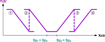
The energy-free zone is defined by the setpoints on changeover of the direction of control action (e.g. heating setpoint, cooling setpoint), see figure below.
Sequence control algorithm
The sequence control algorithm implemented in the function block CTR complies 100% with the control standard [3]. The following topics are covered in [3]:
- Coordination mechanisms of sequence control elements
- Control token passing and receiving for different controller types
- Examples and description of special cases, in particular “mixed” sequences or special control parameter settings.
Control outputs
Manipulated variable [Yctr] and its parts [Yctrp], [Yctri], [Yctrd]
[Yctr] represents the main control output which typically specifies the position of an actuator. For a PID controller, parts of the manipulated variable [Yctr] are displayed for diagnostic purposes:
- The proportional part [Yctrp]
- The integral part [Yctri]
- The derivative part [Yctrd]
For controller types which do not have all parts of the manipulated variable, the according outputs are set to zero. For controllers that do not have the control task (disabled, out of service or non-controlling sequence elements), the control parts are also set to zero.
Error state [ErrSta]
Pin | E | Description | |
ErSta | a | Fault state. | |
0 (No) | Sequence configuration error. | ||
1 (Yes) | No sequence configuration error. | ||
Control state [CtrSta]
CtrSta | f | Controller state. Controller state of the controller or the sequence controller element. | |
1 (CtrOff) | Controller is switched off. | ||
2 (CtrCmd) | Controller is out of service or [YctrMin] ≥ [YctrMax]. | ||
3 (CtrOn) | Controller is controlling actively [Yctr]. | ||
4 (CtrMin) | Controller output [Yctr] = [YctrMin]. | ||
5 (CtrMax) | Controller output [Yctr] = [YctrMax] | ||
Token state [TknSta]
TknSta | a | Token state. Token state of the sequence controller element. | |
1 (NoTkn) | Control element does not have control task (control not enabled). | ||
2 (CtrTkn) | Control element does have the control task (control enabled). | ||
3 (IntgTkn) | Control element does have the control task (control enabled). | ||
4 (BothTkns) | Sequence control element is configured wrongly: Heating element in cooling sequence. | ||
5 (Hel_CSeq) | Sequence control element is configured wrongly: Heating element in cooling sequence. | ||
6 (Cel_Hseq) | Sequence control element is configured wrongly: Cooling element in heating sequence. | ||
7 (RTFault) | Error in the sequence controller element. | ||
Control demand [CtrDmd]
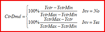
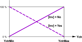
[CtrDmd] outputs the control demand of the controller. This is a normalized signal in percent rangeing from 0% (no demand) to 100% (maximal demand). [CtrDmd] is set to zero if the controller is disabled ([EnFnct] = FALSE), out of service ([OoServ] = TRUE), erroneous ([ErSta] = TRUE) or if [YctrMin] ≥ [YctrMax].
Otherwise, the controller calculates its demand based on [EnFnct].
Control demand calculation if [EnFnct] = TRUE
The controller calculates its demand based on its actual control output [Yctr] relative to the control output limits [YctrMin] and [YctrMax] (see figures below):
Control demand calculation if [EnFnct] = FALSE
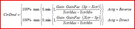
In this case, the controller calculates a so-called virtual demand dependent on control error and settings. For a stand alone P(I)(D) controller, the virtual demand corresponds to the normalized P part of the control output:
If the controller is a stand alone 2-position or staged behavior, the virtual demand is defined as:
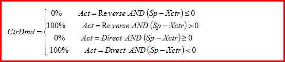
If the controller is part of a sequence controller, the virtual demand is corrected because its virtual demand output has to be in compliance with the whole sequence controller. The following corrections are done:
- The controller acts indirectly ([Actg] = Reverse), a lower sequence control element has the control task and controls actively: CtrDmd = 100%.
- The controller acts directly ([Actg] = Direct), a higher sequence control element has the control task and controls actively: CtrDmd = 100%.
- The controller acts indirectly ([Actg] = Reverse), a higher indirectly acting sequence control element has the control task and controls actively: CtrDmd = 0%.
- The controller acts directly ([Actg] = Direct), a lower directly acting sequence control element has the control task and controls actively: CtrDmd = 0%.
Displayed control demand [CtrDmd]
If the control demand calculation criteria are met, the controller calculates its demand as described avove. Based on the input [DmdMod], the control demand then can be displayed:
- [DmdMod] = Off: Demand calculation turned off, [CtrDmd] = 0% regardless of the calculated demand CtrDmd.
- [DmdMod] = 2-position: [CtrDmd] = 0% if CtrDmd = 0%, or [CtrDmd] = 100% if CtrDmd > 0%
- [DmdMod] = Continuous: [CtrDmd] = CtrDmd
Start-up and error handling
After power-up of the hardware, the function block outputs are initialized in the first control cycle. After the initialization cycle, the function waits for 3 cycles to neutralizes an unfavorable processing order. Afterwards, it is assumed the in particular the sequence control communication inputs [FmLower] and [FmHigher] are valid and the function is performed by utilizing the values at the inputs.
Inputs and outputs of the function block
Note: The CTR is provided with engineering unit and default value settings for temperature control. In case the block is used for other control purposes e.g. light or humidity the engineering units and default value must be adapted accordingly. This is important, otherwise the Unit Conversion process from SI to another Unit System will not work correctly.
Inputs
Pin | Description | Data type | Default value | Engineering unit or Text group | Min. | Max. |
EnFnct | Enable function | Boolean | 1 (Yes) | No, Yes |
|
|
OoServ | Out of service | Boolean | 0 (Off) | Off, On | Off | On |
DefVal | Default value | Real | 0.0 | % | 0.0 | 100.0 |
Sp | Setpoint | Real | 20.0 | °C | -50.0 | 150.0 |
68.0 | °F | -58.0 | 302.0 | |||
Xctr | Controller input | Real | 20.0 | °C | -50.0 | 150.0 |
68.0 | °F | -58.0 | 302.0 | |||
GainFac | Gain factor | Real. | 1.0 | — | -3.402822E38 | 3.402822E38 |
Gain | Gain | Real | 10.0 | %/K | 0.0 | 3.402822E38 |
5.5 | %/°F | 0.0 | 3.402822E38 | |||
Tn | Integral action time Tn | Time | 2m | T#0d_0h_0m_0s_0ms |
|
|
Tv | Derivative action time Tv | Time | 0ms | T#0d_0h_0m_0s_0ms |
|
|
Nz | Neutral zone | Real | 0.5 | K | 0.0 | 10.0 |
1.0 | °F | 0.0 | 18.0 | |||
Ti0to100 ... | Rise time from 0 to 100% | Time | 1m | T#0d_0h_0m_0s_0ms |
|
|
Ti100to0 | Fall time from 100 to 0% | Time | 1m | T#0d_0h_0m_0s_0ms |
|
|
YctrMax | Controller output maximum | Real | 100.0 | % | 0.0 | 100.0 |
YctrMin | Controller output minimum | Real | 0.0 | % | 0.0 | 100.0 |
YctrOfs | Controller output for offset | Real | 0.0 | % | 0.0 | 100.0 |
Actg | Direction of control action | Boolean | 1 (Reverse) | Direct, Reverse |
|
|
CtrTyp | Controller type | Multistate | PID controller | PID controller / Staged controller | PID controller | PID controller |
CtrMod | Controller mode | Boolean | 0 (Continuous) | Continuous / 2-position |
|
|
HysSwiOn | Hysteresis switch on | Real | 0.0 | % | 0.0 | 00.0 |
HysSwiOff | Hysteresis switch off | Real | 0.0 | % | 0.0 | 00.0 |
SwiDly | Switch delay | TIME | 300 | Hh:mm:ss | 0 | Max. |
NumSts | Number of stages | INT | 1 | — | 1 | 10 |
DmdMod | Demand mode | Multistate | 2-position | Off / 2-position / Continuous | Off | Continuous |
Inv | Inverse | Boolean | 0 (No) | No, Yes |
|
|
EnTrack | Tracking enable | Boolean | 0 (No) | No, Yes |
|
|
Track | Tracking | Real | 0.0 | % | 0.0 | 100.0 |
FmHigher | From higher neighbor | Record |
|
|
|
|
FmLower | From lower neighbor | Record |
|
|
|
|
TshVal | Threshold value | Real | 0.1 |
| 0.0 | 3.402822E38 |
BaObjRef | BA object reference | Record |
|
|
|
|
Outputs
Pin | Description | Data type | Default value | Engineering unit or | Min. | Max. |
ErSta | Fault state | Boolean | No | No / Yes | Yes | No |
CtrSta | Controller state | Multistate | CtrOff | CtrOff / CtrCmd / CtrOn / CtrMin / CtrMax | CtrOff | CtrMax |
TknSta | Token state | Multistate | NoTkn | NoTkn / CtrTkn / Hel_CSwq / Cel_HSeq / RTFault | NoTkn | RTFault |
Yctr | Controller output | Real | 0.0 | % | 0.0 | 100.0 |
Valid | Valid | Boolean | No |
|
|
|
CtrDmd | Controller demand | Real | 0.0 | % | 0.0 | 100.0 |
ToHigher | To higher neighbor | Struct |
|
|
|
|
ToLower | To lower neighbor | Struct |
|
|
|
|
Yctrp | Controller output proportional part | Real | 0.0 | % | -3.402822E38 | 3.402822E38 |
Yctri | Controller output integral part | Real | 0.0 | % | -3.402822E38 | 3.402822E38 |
Yctrd | Controller output derivative part | Real | 0.0 | % | -3.402822E38 | 3.402822E38 |
OoServOut | Out of Service, output | Boolean | Off |
|
|
|
GainOut | Gain, output | Real | 10.0 | %/K | 0.0 | 3.402822E38 |
TnOut | Integral action-time Tn, output | Time S7BN | T#OD_OH_2M_0S_0MS |
|
|
|
TvOut | Derivative action-time Tv, output | Time S7BN | T#OD_OH_0M_0S_0MS |
|
|
|
NzOut | Neutral zone, output | Real | 0.5 | K | 0.0 | 40.0 |
Ti0to100Out | Rise time from 0 to 100%, output | Time S7BN | T#OD_OH_1M_0S_0MS |
|
|
|
Ti100to0Out | Fall time from 100 to 0%, output | Time S7BN | T#OD_OH_1M_0S_0MS |
|
|
|
YctrMaxOut | Controller output maximum, output | Real | 100.0 | % | 0.0 | 100.0 |
YctrMinOut | Controller output minimum, output | Real | 0 | % | 0.0 | 100.0 |
YctrOfsOut | Controller output for offset, output | Real | 0.0 | % | 0.0 | 100.0 |
CtrTypOut | Controller type, output | Enum | PID controller |
| PID controller | Staged controller |
HysSwiOnOut | Hysteresis switch-on, output | Real | 0.5 | K | -100.0 | 100.0 |
HysSwiOffOut | Hysteresis switch-off, output | Real | 0.5 | K | -100.0 | 100.0 |
SwiDlyOut | Switch-on/off delay, output | Time S7BN | T#OD_OH_5M_0S_0MS |
|
|
|
NumStsOut | Number of stages, output | Integer | 1 |
| 1 | 10 |
ErrCode | Error code indication | Enum | Object is not accessible |
| No error | Group member overflow |
ErrWrit | Error while writing | Enum | Object is not accessible |
| No error | Group member overflow |
RErrNr | Error number while reading | Integer | 16383 |
| 0 | 65535 |
WErrNr | Error number while writing | Integer | 13683 |
| 0 | 65535 |
Pin description
Inputs
Connection | Description | |
|---|---|---|
EnFnct | Enable function. | |
1 (Yes): | The controller is enabled. | |
2 (No): | The controller is disabled. | |
OoServ | Out of service. | |
(1) On | Controller output [Yctr] and initialization value for integral part of manipulated variable are set to [DefVal]. The outputs [Yctrp], [Yctri], and [Yctrd] are set to 0. [Yctr] can be commanded. | |
(2) Off | Controller output [Yctr] is not commanded. | |
DefVal | Default value. | |
Sp | Setpoint. | |
Xctr | Controller input. | |
GainFac | Gain factor | |
Gain | Gain.
| |
Tn | Integral action time. | |
Tv | Derivative action time. | |
Nz | Neutral zone. | |
Ti0to100 | Rise time from 0 to 100%. | |
Ti100to0 | Fall time from 100 to 0%. | |
YctrMax | Controller output maximum. | |
YctrMin | Controller output minimum. | |
YctrOfs | Controller output offset. | |
Actg | Control action | |
(1) Direct | Direct action such as cooling, dehumidifying. | |
(2) Reverse | Indirect action such as heating, humidifying. | |
Note: Inversion of the controller output [Yctr] occurs with [Inv]. Sequence controller engineering: Parameterizing the sequence controller element. | ||
CtrTyp | Controller type | |
PID controller | The controller acts as PID controller. | |
Staged controller | The controller acts as staged controller. | |
CtrMod | Controller mode | |
Continuous | The controller is not forced to a 2-position controller. | |
2-position | The controller is a forced 2-position controller. | |
DmdMod | Demand mode | |
Off | The demand message is switched off, [CtrDmd] is set to 0%. | |
2-position | For demand = 0%, [CtrDmd] = 0% is set, otherwise 100%. | |
Continuous | The standardized signal 0-100 is outputed to [CtrDmd]. | |
Inv | Inverse | |
Yes | Inversion of the controller output signal [Yctr]. | |
No | No inversion. | |
EnTrack | Tracking enable. | |
Yes | [Track] is integrated in the control process. | |
No | No external tracking. | |
Track | Tracking | |
HysSwiOn | Hysteresis switch on. | |
HysSwiOff | Hysteresis switch off. | |
SwiDly | Switch delay. | |
NumSts | Number of stages. | |
FmLower | From lower neighbor. | |
FmHigher | From higher neighbor. | |
Outputs
ErSta | Fault state | |
No | No error occurred. | |
Yes | Error occurred. | |
CtrSta | Controller state | |
CtrOff | The controller is switched off. | |
CtrCmd | The controller does not control, but [Yctr] = DefVal. | |
CtrOn | The controller is controlling actively [Yctr]. | |
CtrMin | The controller is off [Yctr] = YctrMin. | |
CtrMax | The controller is off [Yctr] = YctrMax. | |
TknSta | Token state | |
NoTkn | The sequence controller element has no token. | |
CtrTkn | The sequence controller element has a controller token. | |
Hel_CSeq | The sequence controller element features an incorrect direction of control action, e.g., heating sequence in the cooling sequence. | |
Cel_HSeq | The sequence controller element features an incorrect direction of control action, e.g., cooling sequence in the heating sequence. | |
Yctr | Controller output. | |
CtrDmd | Controller demand. | |
ToLower | To lower neighbor. | |
ToHigher | To higher neighbor. | |
Yctrp | Controller output proportional part | |
Yctri | Controller output integral part | |
Yctrd | Controller output derivative part | |
Background sequence control
In this section, the most important requirements and principles of the sequence controller are given. For more information on sequence control and the algorithms, please see [3].
Sequence control requirements
Requirements based on experiences with sequence control solutions:
- Setpoints shall be parametrizable per sequence element.
- The sequence element that starts controlling shall be specifiable.
- Each sequence element shall be enabled or set out of service individually.
- Each sequence element does incorporate an individual controller.
- The initial control output when sequence control is switched on shall be specifiable.
- Each sequence element does have an individual neutral zone.
Other requirements
- The sequence controller has to be able to handle a direct and/or a reverse acting (partial) consisting of one or several sequence control elements.
- Both (partial) sequences can consist of an arbitrary number of sequence control elements.
- The setpoints may only be equal or increase form a lower to a higher sequence control element.
- For each sequence control element, the control behavior can be arbitrarily specified: P-, PI-, PID-, PD-controller or staged controller including 2-position controller.
- Each PID sequence control element includes a controller as described in [2].
- Each sequence control element shall be settable out of service individually.
- Only one sequence control element does control at the same time. All other elements are either disabled, out of service, erroneous or at their minimum or maximum output.
- For each sequence control element, control parameters shall be parametrized individually.
- If all control parameters of a PID sequence controller do have the same values (Sp, Gain, Tn, Tv), the sequence control behavior shall be identical to a single (split range) controller.
- The acting type of each sequence control element shall be parametrizable and also changeable at run-time.
- The control output of each sequence control element shall be invertable.
- Each sequence control element shall display its actual control state with the following states:
- CtrOff: the controller is switched off
- CtrCmc: the controller is out of service or [YctrMax] ≤ [YctrMin]
- CtrOn: the controller is switched on and its control output [Yctr] is greater than [YctrMin] and lower than [YctrMax]
- CtrMin: the controller is switched on and its control output [Yctr] equals [YctrMin]
- CtrMax: the controller is switched on and its control output [Yctr] equals [YctrMax]
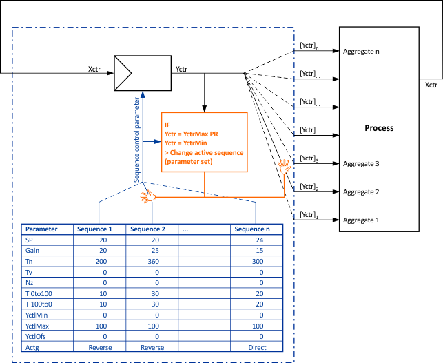
- If the control output of the controlling sequence element reaches its minimum or maximum, the control task is passed to the next (lower or higher) sequence element that is ready for control (enabled and not erroneous or out of service).
Sequence control principles
The most basic principles followed by the sequence controller are:
- At every time point, only one sequence control element does the control (has the control task).
- The control outputs of the non-controlling sequence control elements are constant. Exception: when changing an element back in service or from disabled to enabled, the control output transitions to the mimimum or maximum value.
- Non-available sequence control elements (disabled, out of service or erroneous elements) pass on communication to their neighboring elements (shortcut).
A simplified functional principle can be seen in the figure below:
Application
Control structures
The function block CTR is a universial control element that can be applied for a wide range of control problems. The element can be used in different control structures such as:
- Stand-alone P(I)(D) control
- Stand-alone 2-position or staged control
- Limitation control: The output of a main control element output is limited by a limitation controller acting on the main control elements’ input [YctrMin] or [YctrMax]
- Cascade control: A main control variable is control by an outer control loop controller which outputs a setpoint for a supplementary control variable that is controlled by the inner control loop controller
- Sequence control: One control variable is controlled by several actuators (aggregates) in a specified sequence
Control example
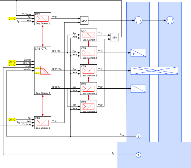
The figure below shows an application example for the function block CTR: Cascade control of an air handling unit. The supply air temperature is controlled in an inner control loop by a sequence control acting on the three aggregates heating coil, cooling coil and energy recovery unit. In the outer control loop, the room temperature is controlled by a sequence control. The outer control loop outputs supply air temperature setpoints as well as a modulating ventilation signal.
The inner control loop includes two limit controllers acting on the outer loops’ ventilation controller. This prevents the ventilation control from increasing the fan speed if the supply air temperature setpoint can not be met by maximum heating or cooling, respectively.