Variable speed fan, air volume flow control (FanVarSpd12)
| This application function operates a variable speed fan, using internal air volume flow controller to drive the measured air volume flow to an air volume flow setpoint. To calculate air volume flow, this AF uses an OEM box flow coefficient (K-factor) and input from a differential pressure sensor. The air volume flow setpoint is calculated based on request signals (from the room controllers) received for heating, cooling and ventilation. Manual input via room operating unit is also possible. There is an optional binary input for the fan state. Another optional binary output can be used to enable the fan operation. This application function is NOT available for: |
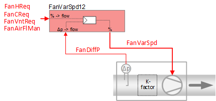
Required elements and how to configure them:
Element | I/O | Signal type |
|---|---|---|
FanVarSpd "Variable speed fan" | On-board output, Fan speed | Variable speed 0…10V |
FanDiffP "Fan differential pressure" | On-board input, Fan differential pressure | 0…10V or P1 |
Function
The figure below shows BACnet objects associated with this application function. Primary signal flow is summarized as follows:
The fan request signal(s) are received (FanVntReq / FanCReq / FanHReq) and processed into the analog output signal for fan speed (FanVarSpd).
Basic function: Accept request signal from associated room controller and pass it through a device mode logic switch; Output the result as a command to the BACnet object that controls the device.
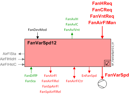
| Command or request (or related) |
| Notification of condition or status, or availability |
| Device mode |
| Interlock (internal signal, not a BACnet object; see Interlocks section for additional information) |


Interlocks
Room automation interlocks are internal signals that coordinate interaction between HVAC devices. They are not visible in ABT Site or web interface, but parameters associated with them are. See comment column for hints on parameters that affect interlock functionality.
Signal | Type | Direction | Description | Comment |
|---|---|---|---|---|
AirFlCReq | Boolean | In | Air flow cooling request |
|
AirFlHReq | Boolean | In | Air flow heating request |
|
AirFlDhuReq | Boolean | In | Air flow dehumidification request |
|
AirFlVntReq | Boolean | In | Air flow ventilation request |
|
AirFlHldC | Boolean | In | Air flow hold for cooling |
|
AirFlHldH | Boolean | In | Air flow hold for heating |
|
AirFlSta | Boolean | Out | Air flow status | See Configuration section for parameters named "...AirFlSta". |
AirFlVavReq | % | In | Air flow vav request | Fan-powered box application. |
FanManOff | Boolean | Out | Fan manual off |
|
Ventilation request - When FanDevMod is "Control mode" the fan is available for ventilation request (FanAvlVnt = Yes). When a ventilation request (FanVntReq) is greater than 4%, FanVarSpd is equal to or greater than FanSpdMinVnt. (switch-off hysteresis to turn fan off is 2%)
If device mode is not Control mode, FanVntReq has no effect.
Note
This feature ensures that the fan can provide a minimum ventilation air flow when there is little or no heating or cooling demand, for example the Neutral zone during temperature sequencing.
Fan heating available status - FanAvlH will equal "Yes" if FanDevMod is "Control mode" and the internal signal for air flow heating request is active (True).
Fan cooling available status - FanAvlC will equal "Yes" if FanDevMod is "Control mode" and the internal signal for air flow cooling request is active (True).
Configuration
 Objects
Description | Object | Type | Default value |
|---|---|---|---|
Fan box coefficient | FanBoxCoef | ACnfVal | 150 [m3/h/SqrtPa] |
Fan maximum air volume flow for cooling | FanAirFlMaxC | ACnfVal | 100 [m3/h] |
Fan minimum air volume flow for cooling | FanAirFlMinC | ACnfVal | 50 [m3/h] |
Fan maximum air volume flow for heating | FanAirFlMaxH | ACnfVal | 100 [m3/h] |
Fan minimum air volume flow for heating | FanAirFlMinH | ACnfVal | 50 [m3/h] |
Fan maximum air volume flow for ventilation | FanAirFlMaxVnt | ACnfVal | 100 [m3/h] |
Fan minimum air volume flow for ventilation | FanAirFlMinVnt | ACnfVal | 50 [m3/h] |
Fan air volume flow for dehumidification | FanAirFlDhu | ACnfVal | 100 [m3/h] |
VAV end air volume flow | VavAirFlEnd | ACnfVal | 100 [m3/h] |
Fan start air volume flow by fan-powered box | FanSttAirFlFpb | ACnfVal | 50 [m3/h] |
Fan end air volume flow by fan-powered box | FanEndAirFlFpb | ACnfVal | 100 [m3/h] |
 Parameters
Description | Parameter | Default value |
|---|---|---|
Nominal air volume flow | AirFlNom | 100 [m3/h] |
Enable state input | EnStaIn | 0:No |
Differential pressure | ||
Switch-on point for differential pressure | SwiOnPtDiffP | 0.2 [Pa] |
Hysteresis for differential pressure | HysDiffP | 0.1 [Pa] |
Interlocks | ||
Switch-on point for air volume flow state | SwiOnAirFlSta | 4 [%] |
Hysteresis for air volume flow state | HysAirFlSta | 2 [%] |
Switch-on delay for air volume flow state | DlyOnAirFlSta | 30 [s] |
Enable fan operation before heating coil 0:No | EnFanOpBfHcl | 0:No |
Internal settings – do not change | ||
Pressure unit | PUnit | [Pa] |
Air volume flow unit | AirFlUnit | [m3/h] |
Interface
Interface | Description | Type | Ref. | Owned by |
|---|---|---|---|---|
FanVarSpd | Variable speed fan | AO | ◉ | Room segment / Device |
EnFanSpd | Enable fan speed | BO | ◉ | Room segment / Device |
FanDiffP | Fan differential pressure | AI | ◉ | Room segment / Device |
FanSta | Fan state Note | BI | ◉ | Room segment / Device |
FanSpAirFl | Fan setpoint for air volume flow | APrcVal | ● | - |
FanSpAirFlRel | Fan setpoint for relative air volume flow | ACalcVal | ● | - |
FanAirFl | Fan air volume flow | ACalcVal | ● | - |
FanAirFlRel | Fan relative air volume flow | ACalcVal | ● | - |
FanAirFlMan | Manual fan air volume flow | APrcVal | ● | - |
FanVarSpdMan | Manual variable speed fan | APrcVal | ● | - |
FanDevMod | Fan device mode 1:Off | MPrcVal | ● | - |
FanAirFlCtr | Fan air flow controller | Controller | ● | - |
FanCReq | Fan cooling request | ACalcVal | ● | - |
FanHReq | Fan heating request | ACalcVal | ● | - |
FanVntReq | Fan ventilation request | ACalcVal | ● | - |
FanAvlC | Fan available for cooling 0:No | BCalcVal | ● | - |
FanAvlH | Fan available for heating 0:No | BCalcVal | ● | - |
FanAvlVnt | Fan available for ventilation 0:No | BCalcVal | ● | - |
FanBoxCoef | Fan box coefficient | ACnfVal | ● | - |
FanAirFlMaxC | Fan maximum air volume flow for cooling | ACnfVal | ● | - |
FanAirFlMinC | Fan minimum air volume flow for cooling | ACnfVal | ● | - |
FanAirFlMaxH | Fan maximum air volume flow for heating | ACnfVal | ● | - |
FanAirFlMinH | Fan minimum air volume flow for heating | ACnfVal | ● | - |
FanAirFlMaxVnt | Fan maximum air volume flow for ventilation | ACnfVal | ● | - |
FanAirFlMinVnt | Fan minimum air volume flow for ventilation | ACnfVal | ● | - |
FanAirFlDhu | Fan air volume flow for dehumidification | ACnfVal | ● | - |
VavAirFlEnd | VAV end air volume flow | ACnfVal | ● | - |
FanSttAirFlFpb | Fan start air volume flow by fan-powered box | ACnfVal | ● | - |
FanEndAirFlFpb | Fan end air volume flow by fan-powered box | ACnfVal | ● | - |
Engineering and commissioning
Parameter EnStaIn must be set to 1:Yes if a binary fan status input is used.