BO 3-Pos without subsystem-specific extension
The following tables show the properties for the channel configuration of analog outputs (AO) with the signal type "BO 3-Pos Relay" and "BO 3-Pos Triac" without any subsystem-specific extension.
The listed properties are displayed in the Hardware and network editor > Inspector window > Properties tab when the data point is selected in the Device view tab.
Number of channels |
|---|
"Number of channels" defines how many channels are used by the data point. If more than one channel is used by the I/O data point, all properties are stored in the first channel. |
Signal type |
|---|
"Signal type" defines the DRA signal type. Available signal types depend on I/O module type. The signal type can be edited. |
Rise time from 0 to 100% |
|---|
"Rise time from 0 to 100%" defines the time used for the signal to go from 0 [%] to 100 [%]. Range: 6.3...6553.5 [s] |
Fall time from 100 to 0% |
|---|
"Fall time from 100 to 0%" defines the time used for the signal to go from 100 [%] to 0 [%]. Range: 6.3...6553.5 [s] |
Reaction time |
|---|
"Reaction time" defines the additional runtime when traveling to 0 % or from 0 %. The reaction time compensates for the clearance between motor and drive. Note: Range: 0.0...50.0 [s] |
Switch-off time |
|---|
"Switch-off time" defines the length of the pause before a change of direction. Range: 0.0...25.5 [s] |
Neutral zone |
|---|
Positioning Neutral Zone. If the difference between the stroke model and the process value (DY) is more than half the deadband plus the hysteresis, this generates an OPEN or CLOSE pulse which is long enough to return the actuator to a position within the deadband. The minimum pulse length is equal to rise time or fall time, multiplied by the hysteresis. See figure Hysteresis and Neutral zone (3-position). Range: |
 0...10 [%]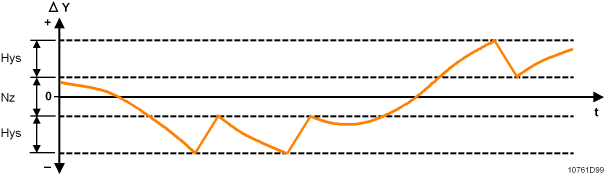
Hysteresis |
|---|
Hysteresis in the stroke model. Range: |
Start synchronization |
|---|
"Start synchronization" defines the method for synchronization of the actuator’s stroke model at startup. Synchronization is automatically initiated at start up.
|
 None
NoneEnd position synchronization |
|---|
"End position synchronization" defines the method of synchronization when reaching an end position (0% or 100%).
|
Relay function |
|---|
"Relay function" defines the logic of the rise command and the fall command.
|
Slope |
|---|
"Slope" defines the slope of linear function used to calculate the measured value or the positioning value. |
Intercept |
|---|
"Intercept" defines the intercept of the linear function used to calculate the measured value or the positioning value. |
Unit |
|---|
"Unit" defines the physical unit of the input or the output. |
Save as
|
|---|
"Save as" saves the set parameters of the I/O data point as an xml-file. |
