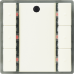
DELTA i-system product description
Product description
Wall switches for the DELTA i-system have the following characteristics:
- Horizontally arranged button pairs
- Labeling field between the buttons
- Mounted together with the design frame “DELTA line”, “DELTA vita”, or “DELTA miro” onto a bus coupling unit (BTM)
- The electrical connection between the wall switch and the bus coupling unit (BTM) is established via the Bus Transceiver Interface (BTI).
- Horizontally aligned buttons may be used as a pair of buttons, or as single buttons. Single buttons can be used for sending values, single-button switching/dimming or single-button control of blinds.
| UP 221/2, DELTA i-system wall switch single
Order number: 5WG1 221-2DB_2 Download data sheet: 5WG12212DB_2 |
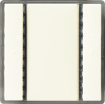
| UP 221/3, DELTA i-switch single with status LED
Order number: 5WG1 221-2DB_3 Download data sheet: 5WG12212DB_3 |
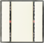
| UP 222/2, DELTA i-system wall switch double
Order number: 5WG1 222-2DB_2 Download data sheet: 5WG12222DB_2 |
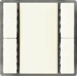
| UP 222/3, DELTA i-system wall switch double with status LED
Order number: 5WG1 222-2DB_3 Download data sheet: 5WG12222DB_3 |
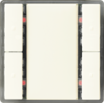
| UP 223/2, DELTA i-system wall switch triple
Order number: 5WG1 223-2DB_2 Download data sheet: 5WG12232DB_2 |
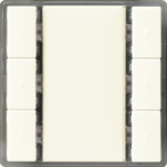
| UP 223/3, DELTA i-system wall switch triple with status LED
Order number: 5WG1 223-2DB_3 Download data sheet: 5WG12232DB_3 |
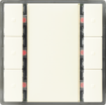
| UP 223/5, DELTA i-system wall switch triple with scene controller/IR receiver decoder
Order number: 5WG1 223-2DB_5 Download data sheet: 5WG12232DB_5 |