Typical input blocks for exception mode
The present exception mode is determined by evaluating the applicable input block.
A selection from the following functions as input blocks are typically used:
- Switch-on fuse
- Fire detector
- Message smoke extraction
- Frost protection monitor
- Overtemperature monitoring
- Fault messages, e.g. from fans
- Maintenance switch, e.g. for fans
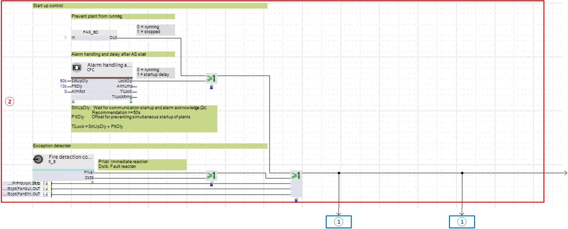
① Normal mode (rapid shutoff of the normal mode for an enabled exception mode)
② Exception mode
The input blocks in the example are:
- Switch-on fuse with PAR_BO
- Contact for fire detector with R_B
- Fixed switch-on delay, for example, for stage start-up
The binary outputs for both input blocks are interconnected by a function block for the logical operator OR. For a fire detector contact, [PrVal] and [Dstb] are also interconnected with OR so that both cases can trigger the exception mode.
As soon as one of the two input blocks sends value 1 to the function block OR, it also provides value 1. This enables the exception mode.
The signal affects a rapid shutdown of normal mode to the extent it is interconnected to input [RpdOff] of the function block CMDSEQ_B.
Function block CMDSEQ_B provides in this case on input [PrVal] value 1 = 'Off' (a rapid shutdown was triggered via input [RpdOff]).
The signal is interconnected to the inputs of the output blocks directly or via other function blocks.
The associated priority is defined on the output blocks (typically priority 15).