Sequencing energy generators
Problem statement
Maintain the main flow temperature of a heat generation plant within or close to a tolerance around a given setpoint.
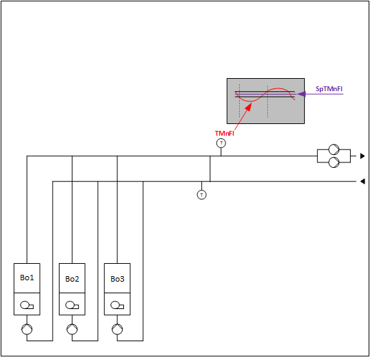
Which components are necessary?
0: Logic for plant operating mode determination
1: Logic for setpoint determination and "Up" and "Down" requests for more or less power
2: Logic for power control and compensation
3: Logic for profile determination
4: Logic for control for every energy producer, e.g, boiler
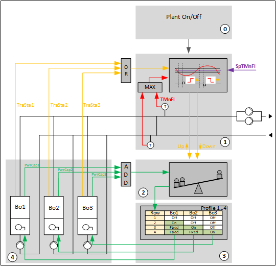
0: Logic for plant operating mode determination
It comprises the logic for switching off the plant and for following different conditions:
- Heating request (optional)
- Different optional fault signals
- Plant manual operation (optional)
- Response to a storage tank charge request (optional)
1: Logic for setpoint determination and "Up" and "Down" requests for more or less power
Logic that determines the present setpoint for the main flow temperature and evaluates if the main flow temperature is within the tolerance around the setpoint. If the main flow temperature is not within the tolerance around the setpoint, it requests more (Up) or less (Down) power from the power generators.
2: Logic for power control and compensation
It responds to "Up" and "Down" by requesting a higher or lower row (or rows) in the profile table until a power capacity increase or decrease is detected. It can automatically compensate the lack of power, e.g., energy producer's fault.
3: Logic for profile determination
It comprises the profile table (SELP8_MS) and the logic for switching between the different profiles, e.g., energy producer's rotation for nearly equal distribution of their operating hours.
4: Logic for control for every energy producer, e.g, boiler
It comprises the interface to the energy producer’s own control and controls its peripherals, e.g., pump, shutoff valve.
Example of the plant structure (HGen24x):
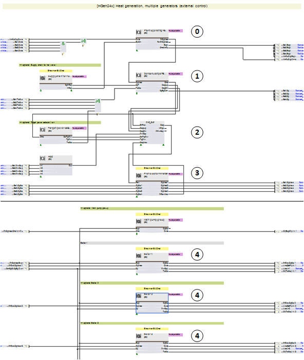
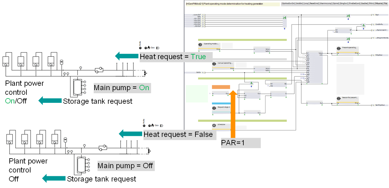
0: Logic for plant operating mode determination (details)
You can set the response to a storage tank charge request in 2 ways:
1. The storage tank charge request turns the plant power control on or off independent of the heat request.
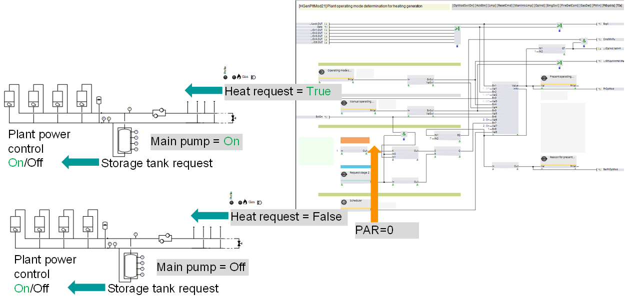
2. The storage tank charge request turns the plant power control on or off only if the heat request is there.
*If the plant is running and the heat request disappears, the plant keeps running until the storage tank is charged.
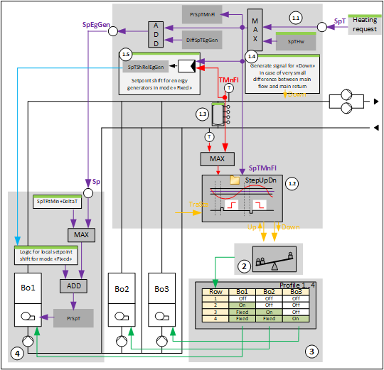
1: Logic for setpoint determination and "Up" and "Down" requests for more or less power
It comprises:
- Logic for setpoint determination
- Logic that evaluates if the main flow temperature is within the tolerance around the setpoint. If not, it requests more (Up) or less (Down) power from the power generators.
- Hot water storage tank
- Logic (optional) that generates an independent signal for less power (Down) when the difference between the main flow temperature and the main return temperature becomes too small.
- Logic (optional) that generates a relative signal (0-100 %) that is read by the energy producers and locally increases their setpoints, e.g., by 0...3 K, if they are in "Fixed" mode. The aim is to fix them and leave only one generator that is "On" to perform the modulation.
Logic for setpoint determination
There are two cases:
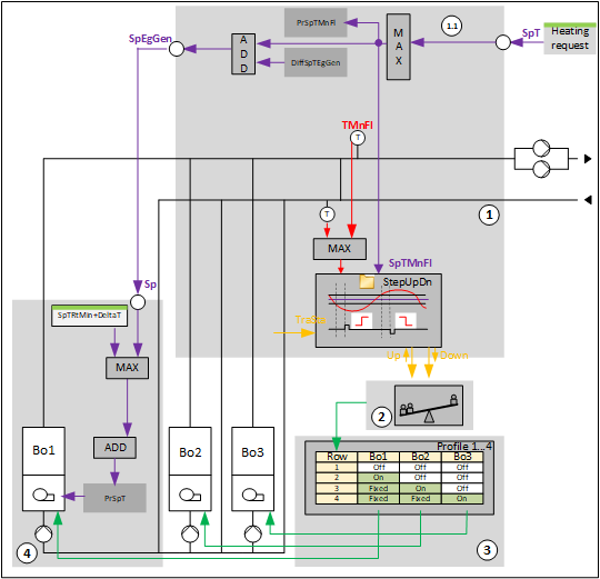
Case 1: There is a logic for hot water coordination. There is a "Setpoint heating request" that is read by the input pin [SpT]. In this case, the optional [SpTHw] is deleted.
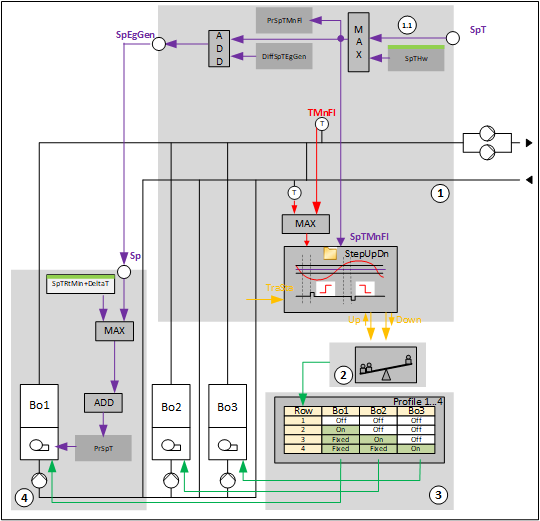
Case 2: There is no "Setpoint heating request" that is read by the input pin [SpT]. In this case, the optional [SpTHw] is kept.
Logic to request more or less power
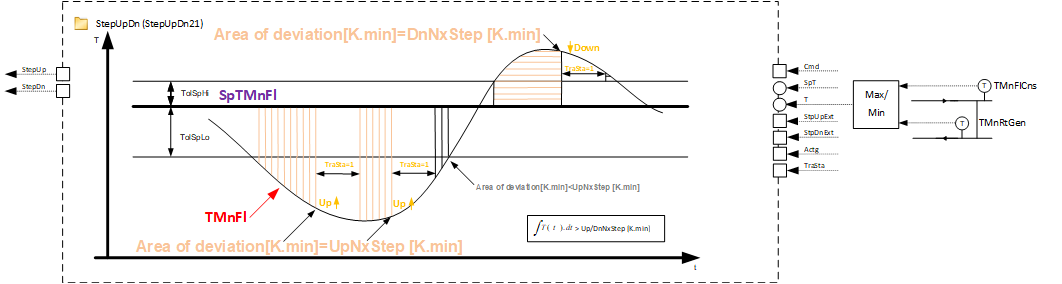
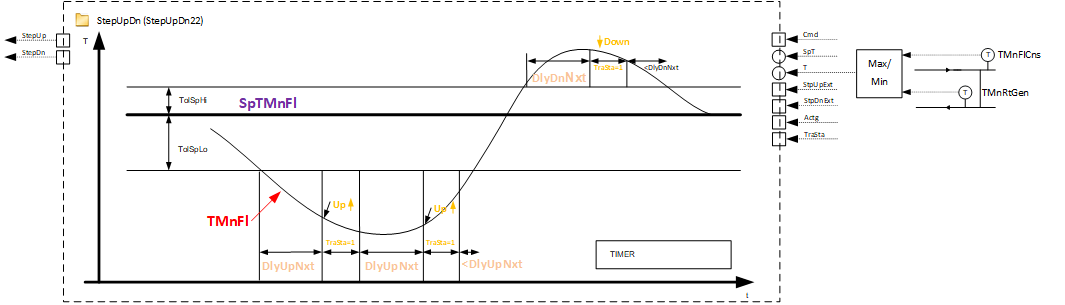
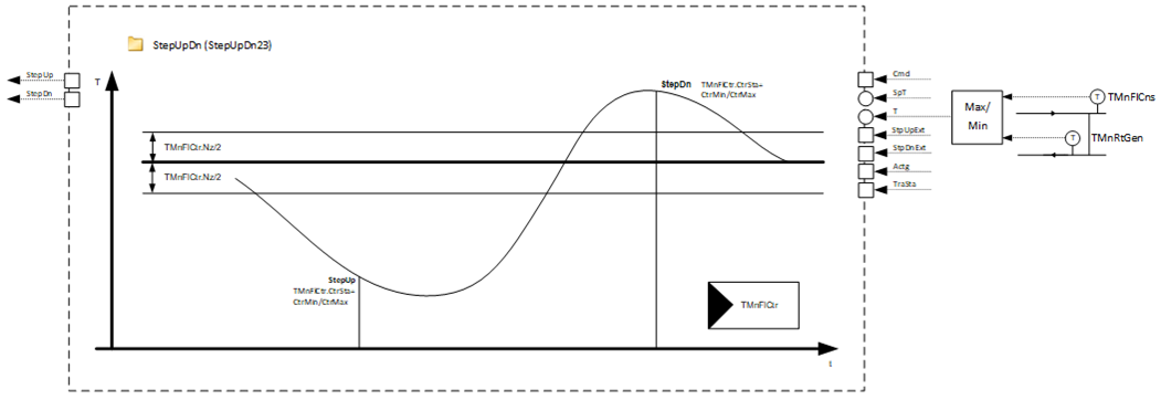
Logic that evaluates if the main flow temperature is within the tolerance around the setpoint. If it is not, it requests more (Up) or less (Down) power from the power generators.
There are 3 alternatives:
1. Program block StepUpDn21:
2. Program block StepUpDn22:
3. Program block StepUpDn23:
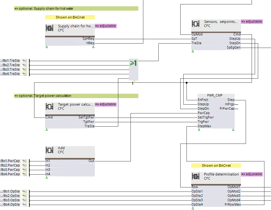
2: Logic for power control and compensation (function block PWR_CMP)
It responds to "Up" and "Down" by requesting a higher or lower row (or rows) in the profile table until a power capacity increase or decrease is detected. It can automatically compensate the lack of power (e.g., energy producer's fault), the excess of power, or go to a given target power.
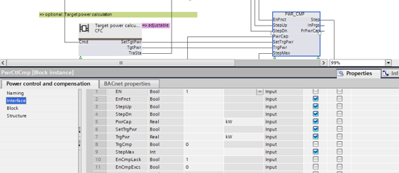
There are two hidden pins that you can adjust.
- Enable compensation for lack of power
- Enable compensation for excess of power
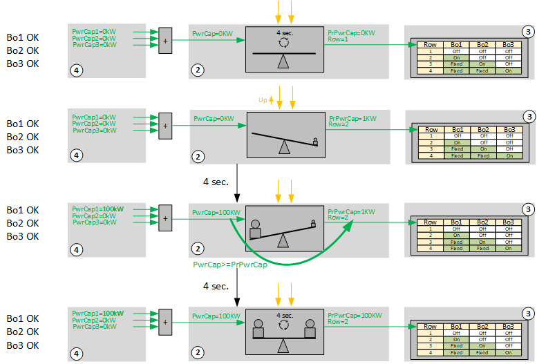
Logic for power control and compensation: Power increase
|
The plant is off. PrPwrCap = 0 KW = PwrCap. The scale is in balance. Every four seconds the logic compares PrPwrCap to PwrCap. |
StepUp = 1. PrPwrCap is artifically increased by 1 KW and is compared to PwrCap = 0 KW. The scale is out of balance. This must be compensated. The logic performs a step and requests a higher row from the profile table. | |
After performing the StepUp, PwrCap = 100 KW > PrPwrCap = 1 KW. The scale is again out of balance, but this time the imbalance is in the desired direction. The logic memorizes the PwrCap by writing it to PrPwrCap. | |
The scale is in balance. PwrCap = 100 K = PrPwrCap. Every four seconds the logic compares PrPwrCap to PwrCap. |
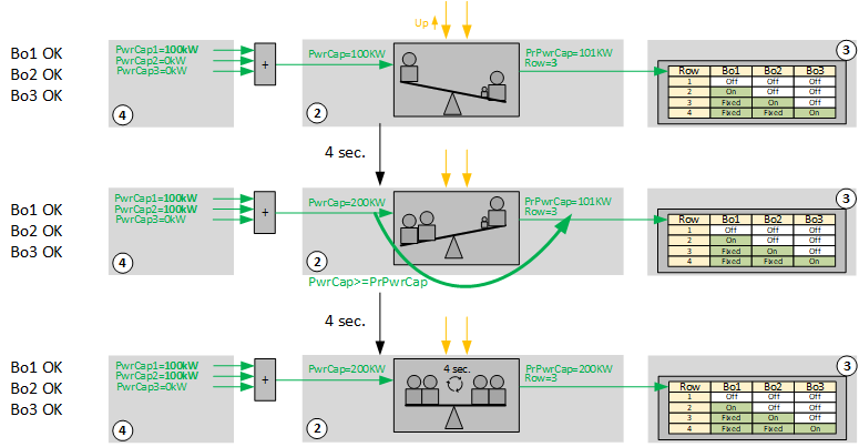
Logic for power control and compensation: Power increase
|
StepUp = 1. PrPwrCap is artifically increased by 1 KW to 101 KW and is compared to PwrCap = 100 KW. The scale is out of balance. This must be compensated and the logic performs a step and requests a higher row from the profile table. |
After the performed StepUp, PwrCap = 200 KW > PrPwrCap = 101 KW. The scale is again out of balance, but this time the imbalance is in the desired direction. The logic memorizes the PwrCap by writing it to PrPwrCap. | |
The scale is in balance. PwrCap = 100 K = PrPwrCap. Every four seconds the logic compares PrPwrCap to PwrCap. |
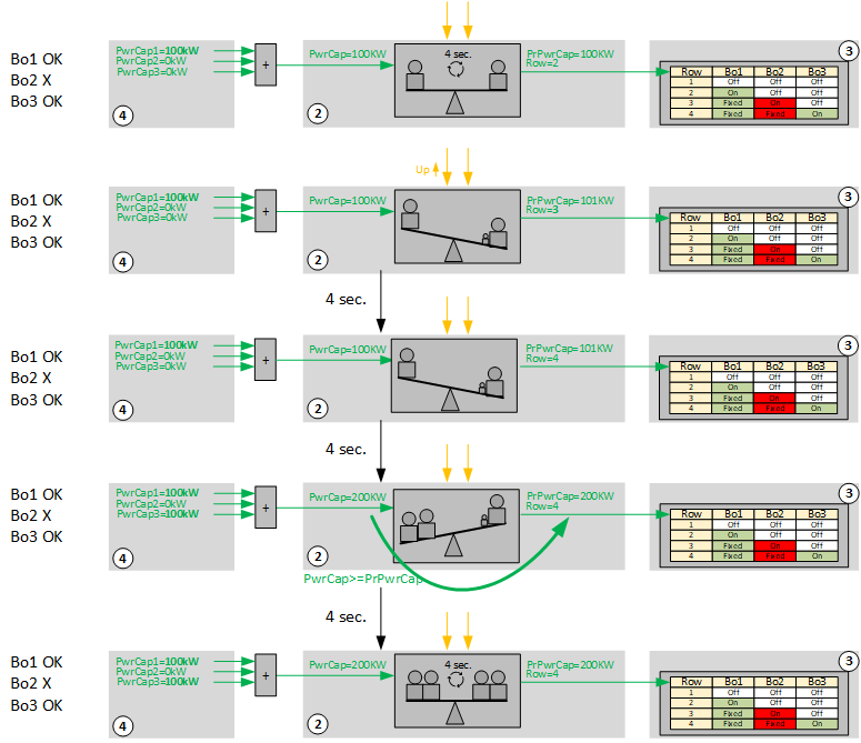
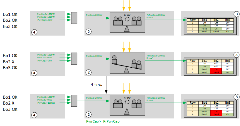
Logic for power control and compensation: Power increase with one generator out of order
|
The plant is on. PrPwrCap = 100 KW = PwrCap. The scale is in balance. Every four seconds the logic compares PrPwrCap with PwrCap. |
StepUp = 1. PrPwrCap is artifically increased by 1 KW to 101 KW and is compared to PwrCap = 100 KW. The scale is out of balance. This must be compensated and the logic performs a step and requests a higher row from the profile table. Unfortunately, Bo2 is out of order and is off. | |
After the performed step, PwrCap remains uchanged at 100 KW < PrPwrCap = 101 KW. The scale is still out of balance. Four seconds later the logic performs another step and requests a higher row from the profile table again. | |
After the performed step, PwrCap = 200 KW > PrPwrCap = 101 KW. The scale is again out of balance, but this time the imbalance is in the desired direction. The logic memorizes the PwrCap by writing it to PrPwrCap. | |
The scale is in balance. PwrCap = 100 K = PrPwrCap. Every four seconds the logic compares PrPwrCap with PwrCap. |
Logic for power control and compensation: Automatic compensation for lack of power
EnCmpLack = 1
|
The plant is on. PrPwrCap = 200 KW = PwrCap. The scale is in balance. Every four seconds the logic compares PrPwrCap to PwrCap. |
A problem with Bo2 occurs. PwrCap drops from 200 KW to 100 KW. The scale is out of balance. This must be compensated and the logic performs a step and requests a higher row from the profile table. | |
After the performed step, PwrCap recovers and is again 200 KW = PrPwrCap. The scale is again in balance. PwrCap = 100 K = PrPwrCap. Every four seconds the logic compares PrPwrCap to PwrCap. |
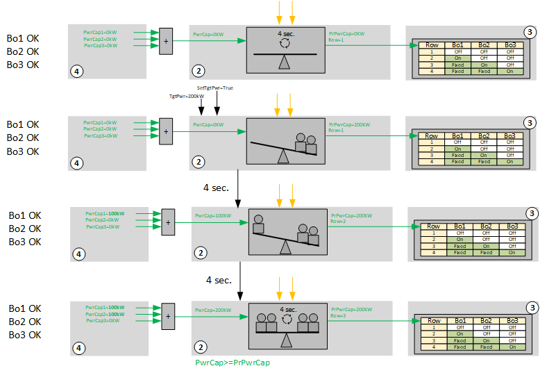
Logic for power control and compensation: Direct switching and controlling of a given target power
|
The plant is off. PrPwrCap = 0 KW = PwrCap. The scale is in balance. Every four seconds the logic compares PrPwrCap to PwrCap. |
A target power of 200 KW is requested. PrPwrCap is set to 200 KW. The scale is out of balance. This must be compensated and the logic performs a step and requests a higher row from the profile table. | |
PwrCap = 100 KW < PrPwrCap = 200 KW. The scale is still out of balance. Four seconds later the logic performs another step and requests a higher row from the profile table again. | |
After the performed step, PwrCap reaches 200 KW = PrPwrCap. The scale is again in balance. Every four seconds the logic compares PrPwrCap to PwrCap. |
3: Logic for profile determination
It comprises the profile table (SELP8_MS) and the logic for switching between the different profiles:
- Manual switching
- Automated energy producer's rotation for nearly equal distribution of their operating hours (ROT_8)
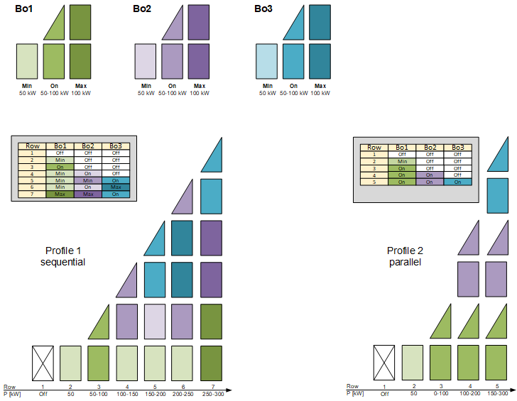
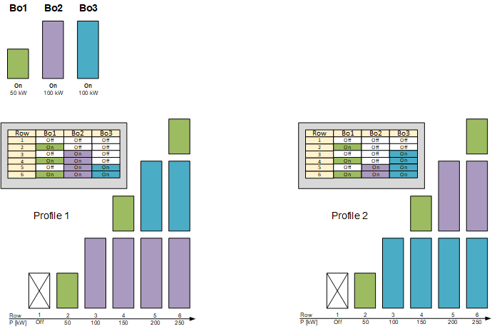
The sequence for switching on the heat generators is determined in the profile table. You can create four different profiles. The entries are entered in each profile so that the total power of the enabled heat generators or stages increases as the row number increases.
The profile does not need to change in the event of a fault, provided the function "Power control and compensation" [EnCmpLack] is enabled. Power control and compensation automatically compensates for the missing power.
The profile table SELP_8MS can transmit the last row with a valid entry via its output [PrRowMax]. "Power control and compensation" receives this value on input [StepMax] and determines the row to which continued switching is permitted.
More examples for different profiles:
Example: Three modulating heat generators with the same power in sequential and parallel control
Possible stages of heat generators: Off, Min, On, Max
Example: Three single-stage heat generators
Heat generator 1 is used for summer operation and as needed.
Heat generators 2 and 3 each have twice the power as heat generator 1.
Possible stages of heat generators: Off, On
4: Logic for control for every energy producer, e.g., boiler
All heating generators are part of the family HGen (6 boilers, 1 heat exchanger, and 2 heat pumps).
The following figure shows the values and elements that you can adjust:
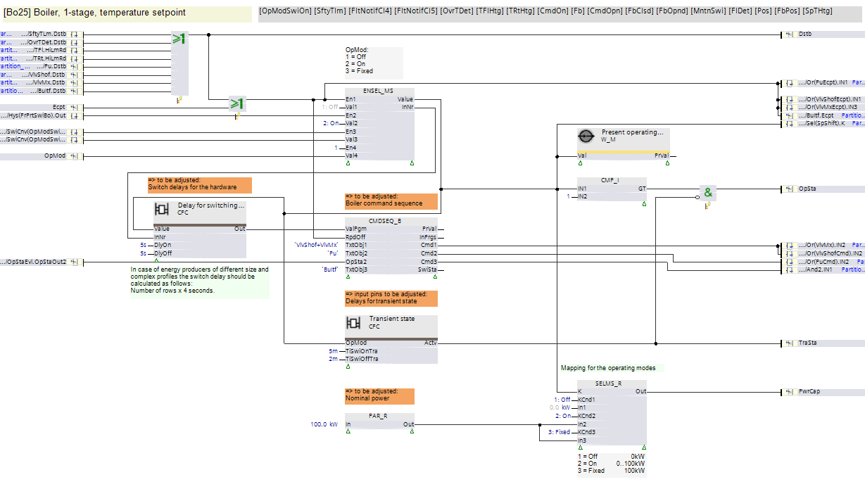
To be adjusted:
- CMDSEQ_B: Sequence and timing for valves, pump, and control unit interface
- Time for TraSta = True after switching on and off
- Nominal power
- Switch-on and switch-off delay for the hardware (valves, pumps, and interface to the control unit)
Avoid unnecessary switch-on and switch-off when changing stages
Increasing the row number on the profile table normally increases power.
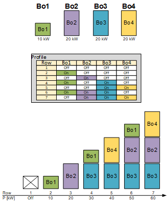
Bo1...4 = Boiler 1...4
Profile = Profile table SELP8_MS
It is possible, however, that a change in a row in the profile table does not bring the desired results, e.g., due to a fault on the energy generator. In this case, the energy generator continues to operate via the switch-off delay until a suitable row is found in the profile table, i.e., until the signals [PwrCap] match the requested power.
Example 1: Boiler 2 (Bo2) in fault
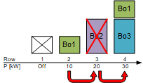
- Boiler 1 switches off if a signal "Step up" arrives during the operation of boiler 1. It changes from row 2 to row 3 in the profile table.
- Boiler 2 cannot be switched on due to a fault and [PwrCap2] reports that no power is available.
- As a result, power control and compensation continues to switch. In the profile table it changes from row 3 to row 4 and boiler 1 and 3 switch on. [PwrCap1] and [PwrCap3] report their power. The available power is now higher than the requested power.
In this workflow, boiler 1 switches off, and after a cycle of 4 seconds, it is back on.
To prevent short-term switch-off and switch-on, a switch-off delay can be added to the boiler. It continues to operate when changing to row 3 and need not be switched on again when changing to row 4.
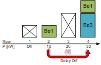
Example 2: Request for target power
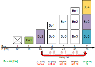
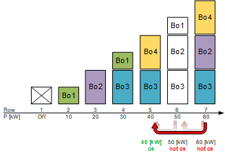
Heat generation operates with boiler 2, i.e., on row 3 in the profile table. An impulse to input [SetTgtPwr] requests the specific power, e.g., 60 kW, now requested on input [TgtPwr]. Steps in the profile table are initiated until the value on input [PwrCap] is greater than or equal to the requested power.
Without set delays, all interim steps are performed, i.e., the corresponding boiler is switched on and off in each cycle of 4 seconds.
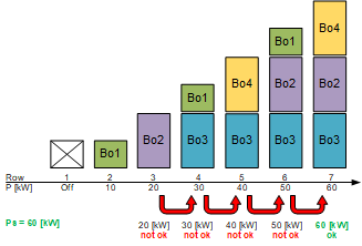
Switching on and off can be avoided by specifying a switch-off delay on the boilers (see example 1). A switch-on delay must be specified in addition to the switch-off delay so that interim stages cannot be switched on if the requested power is not yet achieved on a row.
Example 3: Request for target power, fault boiler 3, no more fault on boiler 3
Heat generation operates with boiler 2, i.e., on row 3 in the profile table. An impulse to input [SetTgtPwr] requests the specific power, e.g. 35 kW, now requested on input [TgtPwr]. Steps in the profile table are initiated until the value on input [PwrCap] is greater than or equal to the requested power. In the event of a fault on boiler 3, this is first the case on row 7.
Without set delays, all subsequent steps are performed, i.e., the boiler is switched on and off in each cycle of 4 seconds.
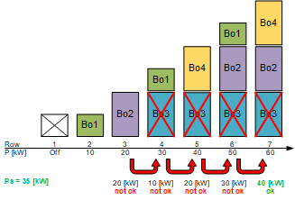
No action occurs if a switch-on and switch-off delay is specified. Boiler 2 continues to operate without interruption and boiler 4 is also switched on, on row 7.
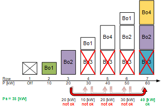
Once the fault on boiler 3 is no longer pending, [PwrCap] now reports 60 kW instead of 40 kW.
If the automation power compensation is activated in the event of an excess [EnCmpPwrExcs], "Step down" is performed in steps in the profile table until the reported power is once again less than or equal to the last saved value in the internal memory. In this case, 40 kW.
Boiler 3 and 4 do not need to be switched on again upon reaching row 5 as a result of the switch-off delay. Boiler 2 switches off after the switch-off delay expires.
Calculating the switch-on and switch-off delay for the hardware
The delay time must be selected to allow all existing rows to be processed at a cycle duration of four seconds. Output [PrRowMax] of the profile table can be used. It announces the last row with a valid entry. The required delay time is the result of:
([PrRowMax] – 2) * 4 s + 2 s
Explanation:
[PrRowMax] – 2 = All rows with an entry minus the first and last row
*4 seconds = Multiplication at a cycle duration of 4 seconds
+2 seconds = Time interval so that the delay time is not at the switching point, but rather in the middle of the cycle.
In other words, for [PrRowMax] = 7:
(7-2)*4+2 = 22 s
The calculated delay time is used for the switch-on and the switch-off delay.
Delayed switch-on and switch-off of stages for a change of stage on slow-acting systems
Certain energy generators, such as some types of refrigeration machines, require more time at start-up until they can supply power, e.g., shutoff dampers open, and then ramping up to nominal power. Switch-off delay of other energy generators must be set to bridge the start times on these energy generators as much as possible. As a result, the switch-off delays are entered manually per the characteristic of the energy generator.
In addition, a switch-on and switch-off delay must be at least large enough to avoid unnecessary switching operations of the stage in the event of a fault in the energy generators. The delay times can be automatically calculated (see prior section).
Example: Switch-on workflow and switch-off workflow for three energy generators
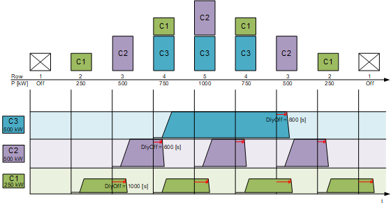
C1...3 = Energy generator 1...3
DlyOff = Switch-off delay
Failure to set switch-off delays results in strong fluctuations in power during a changeover of the energy generator:
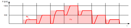
Pw = Requested power (light red area)
Px = Actual power
The power swings are significantly smaller accordingly with set switch-off delays:
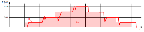
Pw = Requested power (light red area)
Px = Actual power