Object analog output (AO)
Object type analog out (AO) includes the BACnet properties for one analog output.
There is a dependency between 'Name', 'Description' and 'Naming extension'. Any changes to one impacts the other two properties.
Note:
The dependency can be eliminated by entering a project-specific text.
Example 1:
The preconfigured 'Description' "Supply air humidity" sets the 'Name' to "HuSu" if selected. If "Abs" is selected as a supplement to the 'Naming extension', the description is supplemented by "(Absolut)" to "Supply air humidity (absolute)" and the name becomes "HuSu(Abs)". The name also forms the last element of the object name.
Example 2:
The preconfigured 'Description' "Room temperature" sets the 'Name' to "TR" if selected. Selecting "01" (project-specific text) in addition to 'Naming extension', results in the 'Name' "TR(01)". The name also forms the last element of the object name.
Name |
|
|
|---|---|---|
'Name' is a name specific to the instance. It is used to set up a hierarchical object name. | ||
Property ID: 4438 | ||
Description |
|
|
|---|---|---|
'Description' describes a BACnet object. The 'Description' is a translatable string that is saved internally as a text reference or directly as a string. | ||
Property ID: 28 | ||
Name extension |
|
|
|---|---|---|
'Name extension' is an optional extension of the name. It uniquely identifies an object or to distinguish objects. | ||
Property ID: 4437 | ||
Note
Designations from the text catalog can also be used for the 'Naming extension'.
Alarming is implemented under the principle of intrinsic reporting within a BACnet object.
Select the "Properties" tab to add the extension, select 'Yes' in the "Enable event" field. The BACnet properties required for the setting are displayed in ABT Site and the Programming Editor under the "Properties" tab.
Alarming
Overview
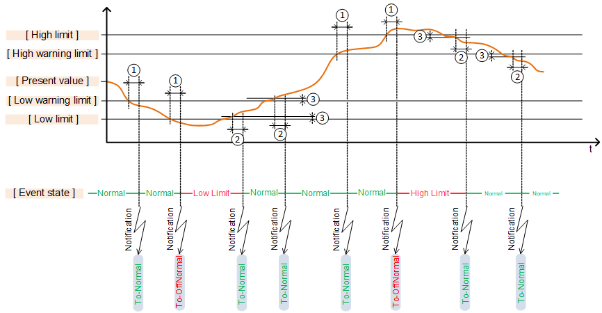
① 'Monitoring time deviation'
② 'Monitoring time deviation to normal'
③ 'Hysteresis to normal'
Enable event |
|
|
|---|---|---|
'Enable event' enables the alarm function. The BACnet properties required to set the function are displayed. For setting 'Yes', the settings 'Extension with event configuration' is set to 'Intrinsic event registration'. | ||
Property ID: 35 | ||
Limit enable |
|
|
|---|---|---|
'Limit enable' determines the limit considered for triggering an alarm. | ||
Property ID: 52 | ||
You can choose either limit, but only one, with the check boxes:
All check boxes cleared: Inactive
'Low limit enable': The setting 'Low limit' is considered. An event is triggered when the limit is breeched and a message "To-OffNormal" is sent.
'High limit enable': The setting 'High limit' is considered. An event is triggered when exceeded and a message "To-OffNormal" is sent.
Warning limit enable |
|
|
|---|---|---|
'Warning limit enable' determines whether an event is triggered and which warning limit is considered. | ||
Property ID: 4543 | ||
You can choose either limit, but only one, with the check boxes:
All check boxes cleared: Inactive
'Low limit enable': The setting 'Lower warning limit' is considered. An event is triggered when the limit is breeched and a message "To-OffNormal" is sent.
'High limit enable': The setting 'Higher warning limit' is considered. An event is triggered when exceeded and a message "To-OffNormal" is sent.
High limit |
|
|
|---|---|---|
'High limit' determines the higher limit of the normal range. If a value exceeds the 'High limit' during a minimum set 'Monitoring time deviation':
The value drops back below 'High limit' by the set 'Hysteresis to Normal".
An acknowledge and reset of the event may be required as per the setting 'Notification class'. | ||
Property ID: 45 | ||
High warning limit |
|
|
|---|---|---|
'High warning limit' indicates that a value is approaching the high limit of the normal range. If a value exceeds the 'High warning limit' during a minimum set 'Monitoring time deviation':
If the value drops below the 'High warning limit' by the set 'Hysteresis to normal', notification "To-Normal" is sent after the set 'Monitoring time deviation' expires. | ||
Property ID: 4544 | ||
Low warning limit |
|
|
|---|---|---|
'Low warning limit' indicates that a value is approaching the low limit of the normal range. If a value drops below 'Low warning limit' during a minimum set 'Monitoring time deviation':
If the value returns above 'Low warning limit' by the set 'Hysteresis to normal', a message "To-Normal" is sent after the set 'Monitoring time deviation' expires. | ||
Property ID: 4545 | ||
Low limit |
|
|
|---|---|---|
'Low limit' determines the lower limit of the normal range. If a value drops below 'Low limit' during a minimum set 'Monitoring time deviation':
The value rises again above 'Low limit' by the set 'Hysteresis to Normal".
An acknowledge and reset of the event may be required as per the setting 'Notification class'. | ||
Property ID: 59 | ||
Hysteresis to normal |
|
|
|---|---|---|
'Hysteresis to normal' determines the minimum difference that a value must maintain when returning the normal range below or above the limit value before the time clock starts with 'Monitoring time deviation to normal'. The value must reside below the hysteresis upon returning to 'High limit' and 'Upper warning limit'. The value must reside above the hysteresis upon returning to the normal range for 'High low' and 'Lower warning limit'. | ||
Property ID: 25 | ||
Monitoring time deviation |
|
|
|---|---|---|
'Monitoring time deviation' determines the time in [s], during which a limit value must be exceeded before an "To-offnormal" is triggered. | ||
Property ID: 113 | ||
Monitoring time deviation to normal |
|
|
|---|---|---|
'Monitoring time deviation to normal' determines the time in [s], during which a limit value plus 'Hysteresis to normal" must be maintained upon returning to the normal range before an a "To-offnormal" event is triggered. | ||
Property ID: 356 | ||
Notification class |
|
|
|---|---|---|
'Notification class' determines the priority of an event and whether the event must be acknowledged or reset. The following are the notification classes: | ||
Property ID: 17 | ||
Enable event detection |
|
|
|---|---|---|
'Enable event detection' enables event detection. The "Event state" is always "Normal" with setting 'No'. | ||
Property ID: 353 | ||
Suppress event notification |
|
|
|---|---|---|
'Suppress event notification' determines whether event notifications are suppressed. | ||
Property ID: 4972 | ||
Suppress event detection |
|
|
|---|---|---|
'Suppress event detection' determines whether event detection is suppressed. | ||
Property ID: 354 | ||
Update Interval ✳ |
|
|
|---|---|---|
Update interval, of type Unsigned, indicates the interval in milliseconds at which the loop algorithm updates the output (Present_Value property). | ||
Property ID: 118 | ||
Enable Trend |
|
|
|---|---|---|
'Enable trend' enables the trend function. A new BACnet object for type TRENDLOG is instantiated, automatically connected to property "Present value" of the selected object and the BACnet properties required for setting are shown in tab "Properties". | ||
Enable logging |
|
|
|---|---|---|
'Enable logging' enables trend logging. Logging of data points begins as of the start date and start time is reached. Trend logging stops if the stop date and stop time are reached or when the buffer is full (if set). Start date and start time (wildcards) are not defined by default. In other words, the setting 'Enable logging' = 'Yes' immediately starts trending. | ||
Property ID: 133 | ||
Logging Type |
|
|
|---|---|---|
'Logging Type' determines when a data point is trended. | ||
Property ID: 197 | ||
Logging interval |
|
|
|---|---|---|
'Logging interval' determines the interval (cycle) at which the value is logged. The setting takes effect by setting 'polled' for 'Logging Type'. | ||
Property ID: 134 | ||
Start time |
|
|
|---|---|---|
'Start time' determines the date and time to start trend logging. | ||
Property ID: 142 | ||
Stop time |
|
|
|---|---|---|
'Stop time' determines the date and time to end trending logging. | ||
Property ID: 143 | ||
Stop when full |
|
|
|---|---|---|
'Stop when full' determines whether to stop trend logging if the buffer is full. | ||
Property ID: 144 | ||
The setting 'Notification threshold' can determine when an event to retrieve data, e.g. by Desigo CC is triggered before the buffer becomes full.
Buffer size |
|
|
|---|---|---|
'Buffer size' determines the maximum number of values that can be saved to the buffer. The setting 'Stop if full' determines how to proceed if the buffer is full. Note The value for property 'Buffer size' must be greater than or equal to the value for property 'Notification threshold'. | ||
Property ID: 126 | ||
Align intervals |
|
|
|---|---|---|
'Align intervals' determines whether the periodic polling interval is aligned at the start of a specific second, minute, hour, or day. The setting has no effect for 'Logging Type' = 'COV'. This ensures that values from multiple, simultaneous trend logs can be saved at the same time and compared. Alignment is only possible for whole number multiples (1…x) of a second, minute, hour, or day. | ||
Property ID: 193 | ||
Interval offset |
|
|
|---|---|---|
'Interval offset', measured in hundredths of a second, permit cyclical trend logs to be spread out. With lots of active trend logs, this prevents a situation where all values are polled at the same time. Polling can be subdivided by staging in groups. 'Interval offset' is only active if the setting 'Align interval' = 'Yes'. | ||
Property ID: 195 | ||
Notification threshold |
|
|
|---|---|---|
'Notification threshold ' determine when the buffer sends a request to retrieve data. As soon as the set number of data entries is reached, an event notification is sent for the management station to retrieve the data. Data points are deleted from the buffer after retrieval. | ||
Property ID: 137 | ||
Other
Present value |
|
|
|---|---|---|
'Present value' indicates the present value of the virtual variable. | ||
Property ID: 85 | ||
Tracking value |
|
|
|---|---|---|
'Tracking value' represents the uncorrected value as measured by the subsystem. It has the same data type as the 'Present value'.
| ||
Property ID: 5107 | ||
Default command |
|
|
|---|---|---|
'Default command' is the default value to be used for property 'Present value' if all priority values for commands have a value of zero in property 'Priority array'. | ||
Property ID: 104 | ||
Change of value, COV ✳ |
|
|
|---|---|---|
'Change of value, COV' specifies the minimum change in 'Present value' property that will cause a COV notification to be issued to change-of-value subscribers of this object. | ||
Property ID: 22 | ||
Reliability |
|
|
|---|---|---|
'Reliability' indicates whether the property value 'Present value' is reliable. If the 'Present value' is not reliable, the property 'Reliability' indicates the cause of the fault and the bit "Fault" of the state indication is set to 'True'. In a normal case, the property 'Reliability' is set to "No fault". | ||
Property ID: 103 | ||
Suppress fault monitoring |
|
|
|---|---|---|
'Suppress fault monitoring' determines whether the fault supervision (fault events) is suppressed ('Yes'/'No'). The setting 'Yes' suppresses the evaluation of 'Reliability' and the value for 'Reliability' remains on "No fault". | ||
Property ID: 357 | ||
'Present maximum value' |
|
|
|---|---|---|
'Present maximum value' sets the highest value for the present value. Values greater than the configured maximum value are limited to the maximum value. | ||
Property ID: 65 | ||
Present minimum value |
|
|
|---|---|---|
'Present minimum value' sets the lowest value for the present value. Values less than the configured minimum value are limited to the minimum value. | ||
Property ID: 69 | ||
Resolution |
|
|
|---|---|---|
'Resolution' indicates the accuracy that a value represents. It defines the smallest recognizable change in engineering units of the property 'Present value' and be modified online. | ||
Property ID: 106 | ||
Units |
|
|
|---|---|---|
'Units' displays the physical unit of 'Present value'. | ||
Property ID: 117 | ||
Signal type |
|
|
|---|---|---|
'Signal type' defines the signal type for its I/O channel. The available signal types depend on the specific hardware, e.g. I/O module type or Onboard-I/O type. | ||
Property ID: 4968 | ||
The signal type must be adapted to the signal source connected on the input. The available signal types are defined in property 'Supported signal types' (BACnet view).
Process value 1 and Process value 2, Signal value 1 and Signal value 2 |
|
|
|---|---|---|
'Process value 1' (X1), 'Process value 2', (X2) 'Signal value 1' (Y1) and 'Signal value 2' (Y2), are used to calculate the linear function (f). The linear function converts a process range from 0...100% to a signal value range. For example, the valve position 0-100% is converted to a positioning signal of 0...10V.
Unit on the x axis: Based on process value. Unit on the y axis: Based on signal type. | ||
Property ID: 4999 (PrcVal1) Property ID: 4998 (PrcVal2) Property ID: 4966 (SigVal1) Property ID: 4965 (SigVal2) | ||

Backup mode |
|
| |
|---|---|---|---|
"Backup mode" defines the backup response for a stoppage of the S7 process. | |||
Retain last value | Retain last value as backup value. | ||
Use default command as backup value | Supply output value as a backup value. | ||
Property ID: 4634 | |||
Additional properties for signal type "3-point control, 2 channels"
Startup synchronization |
|
| |
|---|---|---|---|
'Startup synchronization' defines the method for synchronizing the actuator stroke mode at startup. Synchronization is initiated automatically at startup. | |||
None |
| ||
Single open | Opening command during 1.5 x rise time. | ||
Single close | Closing command during 1.5 x rise time. | ||
Property ID: 4992 | |||
End position synchronization |
|
| |
|---|---|---|---|
'End position synchronization' defines the synchronization method for actuator stroke model upon reaching the end position (0% or 100%). | |||
None | Does not synchronize | ||
Continuous | Always synchronizes at 0% or 100% | ||
Single | Synchronizes one time if PrVal is at 0 or 100% during 1.5 x rise or fall time | ||
Every 10 min | Synchronizes every 10 minutes if PrVal is at 0 or 100% during 1.5 x rise or fall time | ||
Every 20 min | Synchronizes every 20 minutes if PrVal is at 0 or 100% during 1.5 x rise or fall time | ||
Continuous open | Always synchronizes at 100% | ||
Continuous close | Always synchronizes at 0% | ||
Single open | Synchronizes one time if PrVal is at 100% during 1.5 x rise time (100%) | ||
Single close | Synchronizes one time if PrVal is at 0% during 1.5 x fall time (0%) | ||
Open every 10 min | Synchronizes every 10 minutes if PrVal is at 100% during 1.5 x rise time (100%) | ||
Close every 10 min | Synchronizes every 10 minutes if PrVal is at 0% during 1.5 x fall time (0%) | ||
Open every 20 min | Synchronizes every 20 minutes if PrVal is at 100% during 1.5 x rise time (100%) | ||
Close every 20 min | Synchronizes every 20 minutes if PrVal is at 0% during 1.5 x fall time (0%) | ||
Property ID: 4991 | |||
Function command |
|
| |
|---|---|---|---|
'Function command' permits executing a command such as synchronization or calibration. Executing a command may take some time. During this time, the actuator is controlled by the synchronization or calibration command, i.e. no start state can be executed. The bit for "Override" of the state flag is set to TRUE during synchronization and/calibration. | |||
Ready | The actuator is ready for a new request. | ||
Synchronize / Calibrate | Forces a synchronization with a fixed value, defined in property 'Startup synchronization'. | ||
Property ID: 4990 | |||
Rise time from 0 to 100% |
|
|
|---|---|---|
'Rise time from 0 to 100%' defines the time [1/10 s] that a signal requires to go from 0 [%] to 100 [%]. The time should match the runtime of the actuator. | ||
Property ID: 4996 | ||
Fall time from 100 to 0% |
|
|
|---|---|---|
'Fall time from 100 to 0%' defines the time [1/10 s] that a signal requires to go from 100 [%] to 0 [%]. The time should match the runtime of the actuator. | ||
Property ID: 4995 | ||
Hysteresis |
|
|
|---|---|---|
'Hysteresis' determines the hysteresis in the stroke model. | ||
Property ID: 4989 | ||
Control action |
|
| |
|---|---|---|---|
"Control action" defines the logic for the rise and fall command. | |||
Direct | Normal logic: Is opened for a command from 0 to 100 %. | ||
Reverse | Inverted logic: Is closed for a command from 0 to 100 %. Can be used, for example, to match the valve rotation to the mounting position of the actuator. | ||
Property ID: 4988 | |||
Reaction time |
|
|
|---|---|---|
"Reaction time" defines the additional runtime between the actuator end position and the point at which the valve begins to open. Note: Range: 0...500 [0.1 s] | ||
Property ID: 4987 | ||
Switchover delay |
|
|
|---|---|---|
"Switchover delay" defines the length of the break before a change in direction commences. Range: 0...255 [0.1 s] | ||
Property ID: 4986 | ||
Progress value |
|
|
|---|---|---|
"Progress value" displays the current valve position. Read only. Unit: [%] | ||
Property ID: 5083 | ||
Auxiliary functions for signal types "Pulse-width modulation: Spring return" and "Pulse-width modulation: Constant period"
Pulse period |
|
|
|---|---|---|
'Pulse period' defines the length [s] of a switching cycle (pulse period). A minimum switch-on and switch-off time can be defined as an option to prevent premature damage to hardware. The output does not switch if the calculated switch-on/switch-off time is shorter than the minimum switch-on and switch-off time. | ||
Property ID:4984 | ||
Min.switch-off time |
|
|
|---|---|---|
"Min.switch-off time" defines the minimum time that a device must be switched off during a switching cycle. Range: 1...30 [1 s] | ||
Property ID: 66 | ||
Min.switch-on time |
|
|
|---|---|---|
"Min.switch-on time" defines the minimum time that a device must be switched on during a switching cycle. Range: 1...30 [1 s] | ||
Property ID: 67 | ||
Output position |
|
| |
|---|---|---|---|
"Output position" defines whether the connected physical output is handled as NO (Normally Open) or NC (Normally Closed). | |||
NO contact | The connected physical output is handled as NO. | ||
NC contact | The connected physical output is handled as NC. | ||
Property ID: 4970 | |||
Auxiliary functions for signal types "Pulse-width modulation: Thermal" and "Pulse-width modulation: Variable period"
Note:
The pulse period for pulse-width modulation "Thermal" and "Variable period" is variable. It is derived from the minimum switch-on and switch-off times and the process value. However, the pulse period is limited to 6553.5 s.
Maximum pulse rate |
|
|
|---|---|---|
"Maximum pulse rate" defines the pulse rate for a process value 100 %. Examples: Maximum pulse rate 80%: 50%: 33%: | ||
Property ID: 4982 | ||



Minimum pulse rate |
|
|
|---|---|---|
"Minimum pulse rate" defines the pulse frequency for a process value 0%. Examples: Minimum pulse rate 10%: 5%: Min. fixed switch-on time: 1 second | ||
Property ID: 4983 | ||


Minimum switch on/off time |
|
|
|---|---|---|
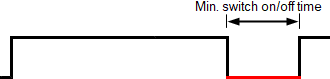
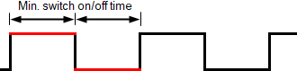
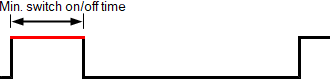
"Minimum switch on/off time" defines the duration of a pulse (on or off). The length of the superposed period for thermal actuators is derived from this time and the process value (in %). Examples for various process values: 75%: 50%: 25%: | ||
Property ID: 4960 | ||
Data aggregation takes place with an extension (data aggregation) within a BACnet object. This includes the corresponding algorithm for data aggregation during a period. The aggregated value of the present period and last period are always displayed. Data aggregation permits operating hours counting as well as virtual metering, calculating key performance indicators and data analysis.
The extension is added with the following setting in tab "Properties":
- 'Enable aggregation' with setting 'Yes'
The setting 'Enable aggregation' = 'Yes', the extension is enabled and the required BACnet properties are displayed.

One BACnet object can have a maximum of one extension with data aggregation. A value that is aggregated to multiple types, requires multiple BACnet objects, each with a data aggregator that references the original object, e.g. one BACnet object for determining the 'Operating hours' and another for determining the 'Average value'.
Aggregation: Operating hours & others |
|
|
|---|---|---|
'Aggregation: Operating hours & others' permits data aggregation. | ||
Property ID: 4580 | ||
Select checkboxes for the following settings:
- 'None': No data aggregation takes place.
- 'Deviation': Data aggregation takes place. 'Deviation' permits data aggregation to determine the area of the deviation of 'Present value' versus the set values per aggregation period.
- 'Average': Data aggregation takes place. 'Average' permits data aggregation to determine the maximum, minimum, and average value of the 'Present value' per aggregation period.
- 'Operating hours': No data aggregation takes place. The time is aggregated, while 'Active' applies as the 'Present value' and remains in the defined partial ranges.
Enable aggregation |
|
|
|---|---|---|
'Enable aggregation' enables or disables aggregation. | ||
Property ID: 4514 | ||
Aggregation period |
|
|
|---|---|---|
'Aggregation period' sets the duration of the aggregation period. Note | ||
Property ID: 4513 | ||
Select checkboxes to set 'Aggregation period' to 15 minutes, 1 hour, or 1 day. 'Aggregation period' is adapted to the present time on the device and automatically triggers the period at the start of a quarter hour, hour, or day. The aggregation starts at the time the device is started.
Analog average
Analog average permits data aggregation to determine the maximum, minimum, and average value per aggregation period.
Minimum value present period |
|
|
|---|---|---|
'Minimum value present period' indicates the minimum value of the 'Present value' since the present period was triggered. | ||
Property ID: 4502 | ||
Maximum value present period |
|
|
|---|---|---|
'Maximum value present period' indicates the maximum value of the 'Present value' since the present period was triggered. | ||
Property ID: 4501 | ||
Average value present period |
|
|
|---|---|---|
'Average value present period' represents the average of the property 'Present value' in the present period. | ||
Property ID: 4500 | ||
Minimum value previous period |
|
|
|---|---|---|
'Minimum value previous period' indicates the minimum value of the 'Present value' from the previous period. | ||
Property ID: 4499 | ||
Maximum value previous period |
|
|
|---|---|---|
'Maximum value previous period' indicates the maximum value of the 'Present value' from the previous period. | ||
Property ID: 4498 | ||
Average value previous period |
|
|
|---|---|---|
'Average value previous period' represents the average of the property 'Present value' from the previous period. | ||
Property ID: 4497 | ||
Analog deviation
The analog deviation permits data aggregation to determine the deviation of values versus the set values. The different is integrated over time as soon as the present value exceeds or drops below a reference value. The deviation or area of the deviation, calculated in this manner, is indicated as "Unit x Time".
Reference low value for deviation |
|
|
|---|---|---|
'Reference low value for deviation' sets the low value for determining the deviation of the 'Present value' during Aggregation period. Note | ||
Property ID: 4496 | ||
Reference high value for deviation |
|
|
|---|---|---|
'Reference high value for deviation' sets the high value for determining the deviation of the 'Present value' during Aggregation period. Note | ||
Property ID: 4495 | ||
Deviation low value present period |
|
|
|---|---|---|
'Deviation low value present period' indicates the deviation to the value of 'Reference low value for deviation' in the present period. | ||
Property ID: 4494 | ||
Deviation high value present period |
|
|
|---|---|---|
'Deviation high value present period' indicates the deviation to the value of 'Reference high value for deviation' in the present period. | ||
Property ID: 4493 | ||
Deviation low value previous period |
|
|
|---|---|---|
'Deviation low value previous period' indicates the deviation to the value of 'Reference low value for deviation' in the previous period. | ||
Property ID: 4492 | ||
Deviation high value previous period |
|
|
|---|---|---|
'Deviation high value previous period' indicates the deviation to the value of 'Reference high value for deviation' in the previous period. | ||
Property ID: 4491 | ||
Deviation unit |
|
|
|---|---|---|
'Deviation unit' sets the unit for deviation values such as 'Deviation high value present period', 'Deviation low value previous period', 'Deviation high value present period', 'Deviation low value present period'. | ||
Property ID: 4481 | ||
Select the checkbox with the required unit for the deviation.
Internal calculation of the deviation is done in units times seconds, where units is the unit as specified in the Units-Property.
For example, internal calculation of the deviation is done for degrees in seconds when the unit property is set to degrees; however, this is not a supported BACnet unit. The value of the Deviation-Units property can be set to K/min or °F/min. Therefore, to display the deviation values in minutes the conversion factor property must be set to 0.01667.
Note
The reference values and deviation use different units.
Example (room temperature):
The value of Units property is given as 21 °C. The deviation is measured in K sec and the amount in the present period, for example, to 26K.min.
Analog operating hours
The analog operating hours permit data aggregation to determining the linger duration of the present value in the various value ranges.
The properties are divided into 2 groups:
- Operating hours count and maintenance indication A
- Statistical evaluation (data analysis) B
A: Operating hours count and maintenance indication
Note
The time is measured as active time during which the present value is greater than the PrValMin ('Present minimum value').
Elapsed active time present period |
|
|
|---|---|---|
'Elapsed active time present period' is the expired time in [s] in the present period during which the 'Present value' is considered 'active' (PrVal>PrValMin). | ||
Property ID: 4512 | ||
Elapsed active time previous period |
|
|
|---|---|---|
'Elapsed active time previous period' is the expired time in [s] in the previous period during which the 'Present value' was considered 'active' (PrVal>PrValMin). | ||
Property ID: 4511 | ||
Operating hours |
|
|
|---|---|---|
'Operating hours' represents the aggregated number in [s] during which the property 'Present value' was 'active' (since the property 'Operating hours' was last reset). 'Operating hours' is synonymous with the expired active time. | ||
Property ID: 33 (Standard BACnet property, used for binary objects only) Property ID: 4490 (Proprietary BACnet property, used for analog and multistate objects) | ||
Time stamp for op.hour reset ✳ |
|
|
|---|---|---|
"Time stamp for op.hour reset" includes the date and time at which the property "Operating hours" was most recently set to a zero value. | ||
Property ID: 114 | ||
Elapsed active time limit present period |
|
|
|---|---|---|
'Elapsed active time limit present period' sets the time limit for the present period in [s] for the 'Expired active time present period' after which the 'Maintenance indication' is enabled. | ||
Property ID: 4509 | ||
Elapsed active time limit |
|
|
|---|---|---|
'Elapsed active time limit' sets the time limit in [s] for 'Operating hours' after which the 'Maintenance indication' is enabled. | ||
Property ID: 4510 | ||
Maintenance indication |
|
|
|---|---|---|
'Maintenance indication' supplies a maintenance note. The following maintenance notes can be indicated: 'Normal mode', 'Present period limit exceeded', 'Time limit exceeded'. | ||
B. Statistical evaluation (data analysis)
Number of ranges |
|
|
|---|---|---|
'Number of ranges' is a configurable number for subdividing a range from present minimum value to present maximum value into equally sized partial ranges. Time is aggregated in [s] for each partial range during which the present value remains in the applicable partial range. | ||
Property ID: 4489 | ||
Elapsed active time per range present period |
|
|
|---|---|---|
'Elapsed active time per range present period' is the expired time in [s] in the present period during which the 'Present value' was in the applicable partial range (PrVal>PrValMin). It is an array with the dimension = Number of ranges and includes one entry per partial range. | ||
Property ID: 4487 | ||
Elapsed active time per range previous period |
|
|
|---|---|---|
'Elapsed active time per range previous period' is the expired time in [s] in the previous period during which the 'Present value' was in the applicable partial range. It is an array with the dimension = Number of ranges and includes one entry per partial range. | ||
Property ID: 4486 | ||
Elapsed active time per range |
|
|
|---|---|---|
'Elapsed active time per range' is the expired time in [s] during which the 'Present value' was in the applicable partial range since the 'Expired active time' was last set to zero. It is an array with the dimension = Number of ranges and includes one entry per partial range. | ||
Property ID: 4488 | ||