[PWR_CMP] Power control and compensation
Function block PWR_CMP receives the request from "Step up/down" for more or less power as a result of the pulse "Step up" or "Step down".
PWR_CMP receives the request from "Step up/down" for more or less power as a result of the pulse "Step up" or "Step down". This request immediately changes the current step and triggers a change to the next or previous row in the profile table.
PWR_CMP receives the request from "Step up/down" for more or less power as a result of the pulse "Step up" or "Step down". This request immediately changes the current step and triggers a change to the next or previous row in the "profile table".
Power compensation then checks whether the change in the row of the "profile table" resulted in the desired increase or reduction to the currently generated Step output. Power compensation receives the feedback on the power currently produced by the heat generators on input [PwrCap] and compares it with the value in internal memory [PrPwrCap].
In the event of not getting the desired result, power control changes the row until the desired increase or reduction to current power is reached within a delay period of 4seconds.
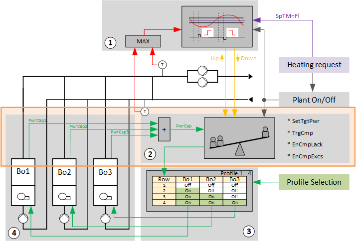
1 | Step up/down |
2 | Power control and compensation |
3 | Profile table |
4 | Heat generation |
Bo1...Bo3 | Heat generator 1...3 |
SetTgtPwr | Set target power |
TrgCmp | Power compensation trigger |
EnCmpLack | Enable automatic power compensation in the event of loss |
EnCmpExcs | Enable automatic power compensation in the event of gain |
PwrCap | Power capability of the boiler |
SpTMnFl | Setpoint for main flow temperature |
Use of internal memory
The internal memory is used by the function block PWR_CMP to correct deviations from the planned increase or reduction.
- Increase the internal memory for Step up:
The internal memory is increased for Step up by 1 [kW]. At the same time, it changes to the next row in the profile table. The power of the switched-on heat generator [PwrCap] is sent back to PWR_CMP. If the power is higher than the value in memory, the current row in the profile table is retained and the value from [PwrCap] is written to internal memory [PrPwrCap]. If the power is still lower than the value in memory, it switches to the next row in the profile table until the power is higher than the value in memory. - Reduce the internal memory for Step down:
The memory is reduced for Step down by 1 [kW]. At the same time, it changes to the previous row in the profile table. The power of the switched-on heat generator [PwrCap] is sent back to "power control and compensation". If the power is lower than the value in memory, the current row in the profile table is retained and the value from [PwrCap] is written to internal memory [PrPwrCap]. If the power is still higher than the value in memory, it is switched to the next row in the profile table until the power is lower than the value in memory.
Detailed workflow using the example for "Step up"
- Power control and compensation receives an impulse "Step up" on input [StepUp] from "Step up/down".
- Power control and compensation sends a command to the profile table to change to the next row.
- The stage is started for the heat generator as defined in this row.
- As a result, power control receives feedback on input [PwrCap] on the new, current power produced by the heat generator.
It remains on this row if the value of the newly reported, currently produced power is greater than the value in memory.

This is generally true as long as the heat generator is not in fault. Power control and compensation changes to the next row in the profile table if the new, currently produced power remains unchanged. The workflow is repeated until the reported, currently produced power is greater than the value in memory. As soon as this is the case, the reported currently produced power is saved again and displayed as the currently produced power on output [PrPwrCap].
Profile table SELP_8MS can transmit the last row with a valid entry via its output [PrRowMax]. "Power control and compensation" receives this value on input [MaxPos] and determines the row to which continued switching is permitted.
Technical implementation:
- [PwrCap] and [PrPwrCap] are compared in cycles, at a cycle period of 4 [s].
- [PrPwrCap] in the internal program logic is increased for an impulse "Step up" by 1 [kW].
- The logic demands more power due to the resultant imbalance between [PwrCap] and [PrPwrCap].
At a cycle duration of 4 [s], it sends a "Step up" impulse until [PwrCap] is greater than [PrPwrCap]. - The system is once again in balance and [PwrCap] is written to the internal memory as [PrPwrCap].
Auxiliary functions
The following auxiliary functions can be activated or inactivated:
- Request for target power:
An impulse on input [SetTgtPwr] deploys the function to the power specified on input [TgtPwr].
The power on [TgtPwr] is saved and steps are initiated in the profile table until the value on [PwrCap] is greater than or equal to. - Forced compensation:
A pulse on input [TrgCmp] restores the original power on [PrPwrCap] in sequential steps, e.g. due to a loss of a heat generator caused by a fault and if no [EnCmpLack] was enabled. - Automatic power compensation in the event of a power shortage [EnCmpLack]:
Power shortage is detected based on input [PwrCap] and balanced by sequential steps, e.g. due to a loss of a heat generator caused by a fault. - Automatic power compensation in the event of a power excess [EnCmpExcs]:
Power gain is detected based on input [PwrCap] and balanced by sequential steps, e.g. due to manually switching on a heat generator.
Interfaces
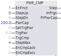
Input | Description | Data type | Default value |
|---|---|---|---|
EnFnct | Enable function | Boolean | 0 |
StepUp | Step up | Boolean | 0 |
StepDn | Step down | Boolean | 0 |
PwrCap | Power capability of the boiler | Real | 0 [kW] |
SetTgtPwr | Set target power | Boolean | 0 |
|
TgtPwr | Power target after trigger (Set target power) | Real | 0 [kW] |
|
TrgCmp | Power compensation trigger (If lack or excess it will compensate) | Boolean | 0 |
StepMax | Maximum possible stage in profile | Multistate | 4 |
EnCmpLack | Enable automatic power compensation in the event of loss | Boolean | 1 |
EnCmpExcs | Enable automatic power compensation in the event of gain | Boolean | 0 |
Output | Description | Data type | Default value |
|---|---|---|---|
|
Step | Power stage (current) | Multistate | 0 |
InPrgs | In progress Power control and compensation active (stage change) | Boolean | 0 |
PrPwrCap | Present requested power capacity | Real | 0 [kW] |
Sequence operation multiple energy generators
The individual energy generators are switched on or off as per the present power demand and selected settings.
The following functions are available:
- Step up/down (using the interconnected chart "Step up/down")
- Power control and compensation (using the interconnected chart "Power control and compensation balance")
- Profile table (implemented with SELP8_MS)
- Energy generator 1..x