Creating staged controls
Modulating control of the output blocks is included in each of the predefined controls.
Predefined plants must be adapted to use staged control on plant components.
There are two ways to form the stages.
- Controller-internal stage formation
- Controller-external stage formation
The CTR controller can convert the modulating output signal internally to an on / off signal or to stages.
The following are possible:
- 2-position control (on / off)
- Stage control
2-postion control
2-position control is formed internally on the controller by setting the following control parameter:
- [CtrMod] Control mode = '2-position control'
The switching points are configured by hysteresis [HysSwiOn] and [HysSwiOff] and control action [Actg].
Stage control
The controller-internal stage is formed by setting the following controller parameters:
- [CtrMod] = 'Modulating'
- [CtrTyp] = 'Stage control'
- [NumSts] (Number of stages) = 'X' (desired number of stages)
The control range of 100 [%] is linear distributed among the desired number of stages. For example, X = 4 stages have switching points at 25 [%], 50 [%], 75 [%] and 100 [%].
Stage formation is visible on BACnet.
The switching points cannot be freely selected, rather they are distributed linearly over 100/X.
For controller-external stages are formed by setting the controller parameters as modulating PID controllers:
- [CtrMod] = 'Modulating'
- [CtrTyp] = 'PID' (default value)
The controller provides a modulating signal (e.g. 0...100%). The signal is converted controller external to a staged signal.
The switching points are freely selectable, e.g. switching point for stage 3 at 65 [%].
Stage formation is not visible on BACnet.
The following changes are necessary:
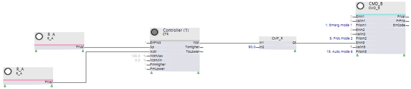
- Conversion of an output signal of the controller function block (0...100%) to a staged output signal. This occurs for a single-stage signal (on/off) via function block CMP_R and for a 4-stage signal via function block CONT_4ST.
- As an output block, use either a binary output block CMD_B or multistate output block CMD_M accordingly.
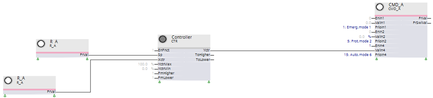
In the plant examples, the plant components are commanded as per the output signal of the controller CTR via analog output block CMD_A from 0...100 [%].
Function block CMP_R receives the analog signal from CTR for the stages (0 [%] , 100 [%]) and converts the signal to a corresponding binary signal 0/1.
Function block CONT_4ST includes the analog signal from CTR for the stages (e.g. for stages 0, 25, 50, 75, 100 [%]) and converts it to a corresponding enumeration 1...5:
- 1 = Off
- 2...5 = Stage 1...4
The setting must be 1 on input [Ofs], otherwise enumeration 0...4 is sent. Output block CMD_M was interpreted as false.

Function block CONT_4ST includes the modulating signal from CTR (0-100 [%]). The analog signal is converted as per the settings at CONT_4ST (e.g. 5, 35, 65, 95 [%]) to enumeration 1...5 and sent to output block CMD_M.
The setting must be 1 on input [Ofs], otherwise enumeration 0...4 is sent. Output block CMD_M was interpreted as false.
- At an input value below 5 [%], CONT_4ST sends enumeration 1.
The plant component is switched off. - At an input value as of 5 [%], CONT_4ST sends enumeration 2.
The first stage of the plant component is switched on. - At an input value as of 35 [%], CONT_4ST sends enumeration 3.
The second stage of the plant component is switched on. - At an input value as of 65 [%], CONT_4ST sends enumeration 4.
The third stage of the plant component is switched on. - At an input value as of 95 [%], CONT_4ST sends enumeration 5.
The fourth stage of the plant component is switched on.
The corresponding stage is switched off once again if the input value drops below the given stage by the set hysteresis [%].
