[Ahu21] Air handling unit, temperature cascade control, pressure control
Plant example Ahu21 has speed-controlled fans, chilled water cooling coil, hot water heating coil, energy recovery with a rotary heat exchanger, and shutoff dampers.
Functions
- Temperature control with room/supply air temperature cascade control
- Pressure control
Plant diagram
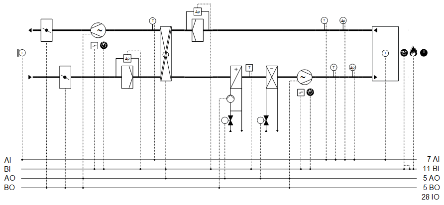
Components
- Fans, speed-controlled
- Shutoff dampers
- Energy recovery with rotary heat exchanger
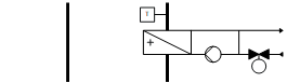
- Hot water heating coil
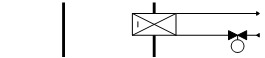
- Chilled water cooling coil
Components and functions of the plant example:
Component | Function | BACnet object |
|---|---|---|
| Fire detection contact Switches the plant off. | [BI] Fire detection contact |
| Operating mode switch Switches the plant to: Auto | Off | On | [MI] Operating mode switch |
| Manual operating mode selection Switches the plant to: Auto | Off | On | [MCnfVal] Manual operating mode selection |
| Scheduler program Switches the plant to: Off | On | [MSchedule] Scheduler |
| Present operating mode Reports the present operating mode: Off | On | [MCalcVal] Present operating mode |
| Reason for present operating mode Reports the reason for the present operating mode: Exception | Operating mode switch | Manual operating mode selection | Scheduler | Switching action operating | [MCalcVal] Reason for present operating mode |
| Temperature control basic setpoints (1) Setpoints for upper and lower room temperature Function diagram for temperature control basic setpoints (1) | [ACnfVal] Setpoint for cooling [ACnfVal] Setpoint for heating |
| Seasonal temperature compensation (2) Corrects the high and low room temperature setpoint per the outside temperature. | [BCalcVal] Seasonal temperature compensation |
| Temperature cascade control (3) (Room/supply air temperature cascade) Calculates the high and low supply air setpoint per the outside temperature. |
> [ACalcVal] Present setpoint high for room temperature > [ACalcVal] Present setpoint low for room temperature > [ACalcVal] Present setpoint high for supply air temperature > [ACalcVal] Present setpoint low for supply air temperature > [ACnfVal] Gain > [ICnfVal] Integral action time Tn > [ACnfVal] Minimum supply air temperature setpoint > [ACnfVal] Maximum supply air temperature setpoint |
| Room temperature sensor Measures room temperature. | [AI] Room temperature |
| Exhaust air differential pressure sensor Measures the differential pressure between duct and environment. | [AI] Extract air pressure (Located in |
| Supply air differential pressure sensor Measures the differential pressure between duct and environment. | [AI] Supply air pressure (Located in |
| Extract air temperature sensor Measures extract air temperature. | [AI] Extract air temperature |
| Supply air temperature sensor Measures the supply air temperature. | [AI] Supply air temperature |
| Supply air fan |
|
Pressure controller Controls the supply air pressure. | > [Controller] Pressure controller
| |
Supply air pressure setpoint Determines the setpoint for supply air pressure. | > [ACnfVal] Setpoint supply air pressure
| |
Command Switches on/off the fan as needed. | > [BO] Command | |
Speed Controls the fan speed between 0 and 100 [%]. | > [AO] Speed | |
Maintenance switch Switches off the fan and the plant. The fan outputs are blocked locally at a high priority (Prio 2). | > [BI] Maintenance switch | |
Fault message Fault messages, e.g. from the external motor control (variable speed drives). Switches off the fan and the plant. | > [BI] Fault | |
| Cooling coil |
|
Reports chilled water demand to cooling distribution. | > [BCalcVal] Chilled water demand | |
Valve |
| |
Temperature controller Controls the supply air temperature. | > [Controller] Temperature controller | |
Valve position Controls the valve position: 0…100 [%] | > [AO] Position | |
| Heating coil
|
|
Reports hot water demand to heat distribution. | > [BCalcVal] Hot water demand | |
Frost protection Prevents the hot water heating coil from freezing. If the frost protection monitor triggers:
| > [BI] Frost protection monitor | |
Purge optimization Purges the heating coil with hot water at cold outside temperature prior to switching on fans. Duration and valve opening are optimized using function [PURGE] purge optimization. | > [BCalcVal] Startup purge active | |
Pump |
| |
Pump command Switches on/off the pump as needed. | > [BO] Command | |
Pump run when the outside air temperature is low: Pump always operates at low outside temperatures (frost protection). |
| |
Kick function (pump kick) Prevents the pump from seizing during long idle periods. |
| |
Valve |
| |
Temperature controller Controls the supply air temperature. | > [Controller] Temperature controller | |
Valve position Controls the valve position: 0…100 [%] | > [AO] Position | |
| Extract air filter |
|
Monitors the differential pressure through the extract air filter and reports a dirty filter. | > [BI] Filter detector | |
| Energy recovery (Rotary heat exchanger) Reuses sensitive and latent energy from extract air for the supply air through the transfer of heat and humidity. Changeover of heating/cooling: Determines whether it can be heated or cooled using extract air:
|
|
Temperature controller Controls the supply air temperature. The supply air setpoint is the result of the average of the high setpoint for supply air temperature and the low setpoint for supply air temperature. | > [Controller] Temperature controller | |
Speed Controls the speed of the rotary heat exchanger: 0…100 [%] | > [AO] Speed | |
Anti-icing protection The temperature sensor measures the exhaust air temperature after energy recovery. The anti-icing protection controller holds the exhaust air temperature sufficiently high by lowering the power (speed). Prevents freezing of any condensation and icing on the exchanger surface. | > [AI] Exhaust air temperature after energy recovery > [Controller] Anti-icing protection controller | |
Reports faults from external energy recovery control. | > [BI] Fault | |
| Outside air filter |
|
Monitors the differential pressure through the outside air filter and reports a dirty filter. | > [BI] Filter detector | |
| Exhaust air fan |
|
Pressure controller Controls extract air pressure. | > [Controller] Pressure controller
| |
Determines the extract air pressure setpoint. | > [ACnfVal] Setpoint extract air pressure
| |
Command Switches on/off the fan as needed. | > [BO] Command | |
Speed Controls the fan speed: 0…100 [%] | > [AO] Speed
| |
Maintenance switch Switches off the fan and the plant. The fan outputs are blocked locally at a high priority (Prio 2). | > [BI] Maintenance switch | |
Fault message Fault messages, e.g. from the external motor control (variable speed drives). Switches off the fan and the plant. | > [BI] Fault | |
| Outside air damper |
|
Command Opens and closes the outside air damper. Adjustable damper runtime in the program. | > [BO] Command | |
| Exhaust air damper |
|
Command Opens and closes the exhaust air damper. Adjustable damper runtime in the program. | > [BO] Command | |
| Sensor for outside temperature Measures outside temperature. | > [AI] Outside air temperature |



 Temperature control (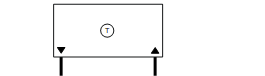











Overview
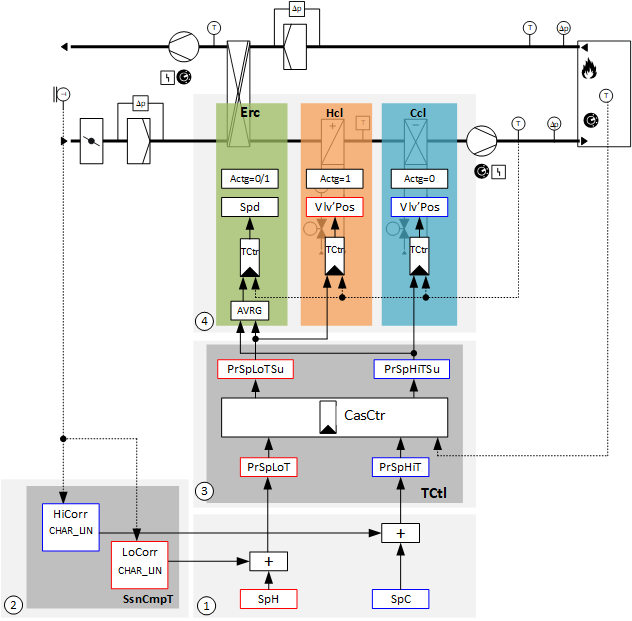
Room/supply air temperature cascade control with seasonal temperature compensation:
Key
1 |
|
SpH | Setpoint for heating |
SpC | Setpoint for cooling |
2 |
|
HiCorr | High correction value |
LoCorr | Low correction value |
CHAR_LIN | Characteristics with linearization |
SsnCmpT | Seasonal temperature compensation |
3 |
|
PrSpLoTSu | Present setpoint low for supply air temperature |
PrSpHiTSu | Present setpoint high for supply air temperature |
CasCtr | Cascade controller |
PrSpLoT | Present setpoint low for room temperature |
PrSpHiT | Present setpoint high for room temperature |
TCtl | Temperature control |
4 |
|
Erc | Energy recovery |
Hcl | Heating coil |
Ccl | Cooling coil |
Actg =1 | Control action for the rotary heat exchanger is heating. |
Actg =0 | Control action for the rotary heat exchanger is cooling. |
Spd | Speed |
Vlv-Pos | Valve position |
TCtr | Temperature controller |
Avrg | Average |
Plant example Ahu21 is used as room/supply air temperature cascade control.
Ahu21 can be adapted to the following applications with just a few modifications:
- Extract air/supply air temperature cascade control
- Pure supply air temperature control
- Pure room temperature control
Ventilation control by extract air, supply air, or room temperature for flat plants
Temperature control basic setpoints (1)
Basic setpoints, that, for example, are operated by the operator:
BACnet objects
Name | Description | Object type | Default value |
|---|---|---|---|
SpC | Setpoint for cooling | ACnfVal | 24 [°C] |
SpH | Setpoint for heating | ACnfVal | 21 [°C] |
This plant example deals with basic setpoint for temperature control of the room setpoints.
Seasonal temperature compensation (2)
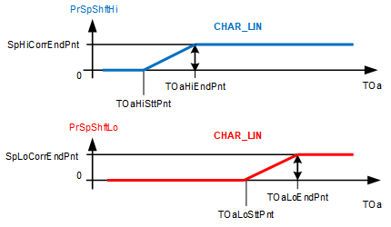
Seasonal temperature compensation corrects the high and low room temperature setpoint per the outside temperature.
The correction begins on the outside temperature start point [TOa...SttPnt] and ends with the outside temperature end point [TOa...EndPnt]. [Sp…CorrEndPnt] determines the height of the correction.
Key
PrSpShftHi | Present setpoint shift high |
SpHiCorrEndPnt | High correction value at the outside air end point |
CHAR_LIN | Characteristics with linearization |
TOaHiEndPnt | Outside air temperature high for end point |
TOaHiSttPnt | Outside air temperature high for start point |
TOa | Outside air temperature |
PrSpShftLo | Present setpoint shift low |
SpLoCorrEndPnt | Low correction value at the outside air end point |
TOaLoEndPnt | Outside air temperature low for end point |
TOaLoSttPnt | Outside air temperature low for start point |
BACnet objects
Name | Description | Object type | Default value |
|---|---|---|---|
SsnCmpT | Seasonal temperature compensation The seasonal temperature compensation is active if a correction is not equal to zero. | BCalcVal | Inactive |
Set values on function block CHAR_LIN
Name | Description | Default value |
|---|---|---|
TOaHiSttPnt | Outside air temperature high for start point (X1 on CHAR_LIN) Outside temperature at which the temperature compensation increases the high setpoint. | 26 [°C] |
TOaHiEndPnt | Outside air temperature high for end point (X2 on CHAR_LIN) Outside temperature up to which the temperature compensation increases the high setpoint. | 32 [°C] |
SpHiCorrEndPnt | High correction value at the outside temperature end point = > Height of the correction (Y2 on CHAR_LIN) | 3 [K] |
TOaLoSttPnt | Outside air temperature low for start point (X1 on CHAR_LIN) Outside temperature at which the temperature compensation increases the low setpoint. | 26 [°C] |
TOaLoEndPnt | Outside air temperature low for end point (X2 on CHAR_LIN) Outside temperature up to which the temperature compensation increases the low setpoint. | 32 [°C] |
SpLoCorrEndPnt | Low correction value at the outside temperature end point = > Height of the correction (Y2 on CHAR_LIN) | 1 [K] |
Combination of basic setpoints (1) and seasonal temperature compensation (2)
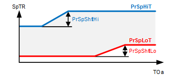
Key
SpTR | Room temperature setpoint |
PrSpHiT | Present setpoint high for room temperature |
PrSpShftHi | Present setpoint shift high |
PrSpLoT | Present setpoint low for room temperature |
PrSpShftLo | Present setpoint shift low |
TOa | Outside air temperature |
BACnet objects
Name | Description | Object type | Default value |
|---|---|---|---|
PrSpHiT | Present setpoint high for room temperature The present setpoint high room temperature or extract air setpoint for cooling operation as corrected by the seasonal temperature compensation | ACalcVal | 23 [°C] |
PrSpLoT | Present setpoint low for room temperature The present setpoint low room temperature or extract air setpoint for heating operation as corrected by the seasonal temperature compensation | ACalcVal | 22 [°C] |
Comfort for the room is defined using the two basic setpoints for the room temperature; both of which are compensated to account for outside temperature.
Temperature cascade control (3)
Temperature cascade control of the room supply air calculates the high and low supply air temperature setpoint as per the room temperature.
Function block CAS_CTR calculates the following setpoints:
- [PrSpHiTSu] Present setpoint high for supply air temperature
- [PrSpLoTSu] Present setpoint low for supply air temperature
The supply air setpoints [PrSpLoTSu] and [PrSpHiTSu] are limited on the low side by the minimum supply air temperature setpoint [SpTSuMin] and by the maximum supply air temperature setpoint [SpTSuMax] on the high side.
If the room temperature [TR] exceeds the present setpoint high for the room temperature [PrSpHiT], the present setpoint high for supply air [PrSpHiTSu] is continuously reduced until the minimum setpoint low for supply air [SpTSuMin] is reached.
If the room temperature [TR] drops below the present setpoint low for room temperature [PrSpLoT], the present setpoint low for supply air [PrSpLoTSu] is continuously increased until the maximum setpoint for supply air [SpTSuMax] is reached.
Setpoints are forwarded to the components responsible for supply air temperature control (4).
The setpoint for energy recovery with rotary heat exchanger is calculated using the average of [PrSpHiTSu] and [PrSpLoTSu].
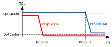
Key
TSu | Supply air temperature |
SpTSuMax | Maximum supply air temperature setpoint |
PrSpLoTSu | Present setpoint low for supply air temperature |
PrSpHiTSu | Present setpoint high for supply air temperature |
SpTSuMin | Minimum supply air temperature setpoint |
PrSpLoT | Present setpoint low for room temperature |
PrSpHiT | Present setpoint high for room temperature |
TR | Room temperature |
BACnet objects
Name | Description | Object type | Default value |
|---|---|---|---|
PrSpHiT | Present setpoint high for room temperature The present setpoint high room temperature or extract air setpoint for cooling operation as corrected by the seasonal temperature compensation | ACalcVal | 23 [°C] |
PrSpLoT | Present setpoint low for room temperature The present setpoint low room temperature or extract air setpoint for heating operation as corrected by the seasonal temperature compensation | ACalcVal | 22 [°C] |
PrSpHiTSu | Present setpoint high for supply air temperature Calculated supply air setpoint for cooling | ACalcVal | 18 [°C] |
PrSpLoTSu | Present setpoint low for supply air temperature Calculated supply air setpoint for heating | ACalcVal | 18 [°C] |
SpTSuMax | Maximum supply air temperature setpoint Limits supply air on the high side. | ACnfVal | 32 [°C] |
SpTSuMin | Minimum supply air temperature setpoint Limits supply air on the low side. | ACnfVal | 15 [°C] |
Gain | Gain Gain factor for the cascade controller | ACnfVal | 3 [K/K] |
Tn | Integral action time Tn Integral action time for the cascade controller | ICnfVal | 1200 [s] |
Supply air temperature control (4)
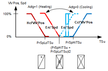
Key
Vlv'Pos, Spd | Position, speed |
Actg =1 | Control action for the rotary heat exchanger is heating. |
Actg =0 | Control action for the rotary heat exchanger is cooling. |
Hcl'Vlv'Pos | Heating coil valve position |
Ccl'Vlv'Pos | Cooling coil valve position |
Erc'Spd | Speed of energy recovery with rotary heat exchanger speed |
PrSpLoTSu | Present setpoint low for supply air temperature |
PrSpHiTSu | Present setpoint high for supply air temperature |
TSu | Supply air temperature |
BACnet objects
Name | Description | Object type | Default value |
|---|---|---|---|
Hcl'Vlv'TCtr | Temperature controller for heating coil Controls the supply air temperature. | Controller | N/A |
The temperature controller acts as a PI controller (PID with derivative action time Tv=0) and compares the temperature setpoint [SpTSu] against the supply air temperature [TSu] and calculates the valve position [Hcl'Vlv'Pos] on the output. The following controller variables are preset: The controller is locked in the following cases: | |||
Erc'TCtr | Temperature controller for energy recovery Controls the supply air temperature. | Controller | N/A |
Conditions for heating are fulfilled: The following controller variables are preset: Conditions for cooling are fulfilled: The following controller variables are preset: Behavior at plant startup: Ramp-up at low outside temperature and if purge optimization [PURGE] occurred: Ramp-up if no purge optimization [PURGE] occurred: | |||
Ccl'TCtr | Temperature controller for cooling coil Controls the supply air temperature. | Controller | N/A |
The temperature controller acts as a PI controller (PID with derivative action time Tv=0) and compares the temperature setpoint [PrSpHiTSu] against the supply air temperature [TSu] and calculates the valve position [Ccl'Vlv'Pos] on the output. The following controller variables are preset: The controller is locked in the following cases: | |||
Icing protection on energy recovery with rotary heat exchangers
Holds the exhaust air temperature sufficiently high by lowering the power (speed).
Prevents:
- Freezing of any condensation
- Icing of the exchanger surface
BACnet objects
Name | Description | Object type | Default value |
|---|---|---|---|
Erc'lcPrtCtr | Anti-icing protection controller Prevents icing on the exchanger surface. | Controller | N/A |
The anti-icing protection controller acts as a PI controller (PID with derivative action time Tv=0) and compares the temperature setpoint set on input [Sp] against the exhaust air temperature after energy recovery [TEhAfErc] and calculates value [YCtrMax] on the output on BACnet object Erc'TCtr (temperature controller for energy recovery). The following controller variables are preset: | |||
Supply air pressure control
Controls the supply air pressure using the supply air fan.
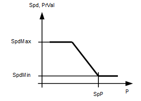
Key
Spd, PrVal | Speed, Present value |
SpdMax | Maximum speed |
SpdMin | Minimum speed |
SpP | Pressure setpoint |
P | Pressure |
BACnet objects
Name | Description | Object type | Default value |
|---|---|---|---|
FanSu'PCtr | Pressure controller for supply air fan Controls the supply air pressure. | Controller | N/A |
The pressure controller acts as a PI controller (PID with derivative action time Tv=0) and compares the setpoint for supply air pressure [SpPSu] against the supply air pressure [PSu] and calculates the fan speed [Spd] on the output. The following controller variables are preset: | |||
Extract air pressure controller
Controls the extract air pressure using an exhaust air fan.
Key
Spd, PrVal | Speed, Present value |
SpdMax | Maximum speed |
SpdMin | Minimum speed |
SpP | Pressure setpoint |
P | Pressure |
BACnet objects
Name | Description | Object type | Default value |
|---|---|---|---|
FanEh'PCtr | Pressure controller for exhaust air fan Controls extract air pressure. | Controller | N/A |
The pressure controller acts as a PI controller (PID with derivative action time Tv=0) and compares the setpoint for extract air pressure [SpPEx] against the extract air pressure [PEx] and calculates the fan speed [Spd] on the output. The following controller variables are preset: | |||
Plant operating modes:
- Off (1)
- On (2)
The operating modes are reported on [MCalcVal] object 'Present operating mode'.
At the same time, the reason for the present operating mode is reported to another [MCalcVal] object:
- Exception (1)
- Operating mode switch (2), resulting from an active (not equal to Auto) operating mode switch
- Manual operating mode selection (3), resulting from an active (not equal to Auto) manual operating mode selection
- Scheduler (4), resulting from an active scheduler
- Switching action is performed (5) and is the result of a transition state on the plant (e.g. longer switch-off due to a delay to dry out the cooler)
The components for control are connected to function block CMDSEQ_B and are also acquired by this function block. See table below.
[CMDSEQ_B] Command sequence for binary
There is a normal mode and exception mode.
Normal operation
Sources for normal mode:
- [MI] Operating mode switch
- [MCnfVal] Manual operating mode selection
- [MSchedule] Scheduler
In normal mode, the components are controlled at priority 15 per the operating mode, sequence, and function in function block CMDSEQ_B. The set timeouts and/or delays are considered.
Exception mode
Sources for exception mode:
- Fire detection contact
- Faults in the components, e.g. fault contact, frost protection monitor, maintenance switch
In exception mode, all outputs are switched off directly at priority 5 and the present operating mode is set to 'Off'. This is reported to function block CMDSEQ_B on input [RpdOff] and the components are switched off immediately as of the function block at priority 15.
The set timeouts and/or delays are not considered.
Special case frost protection:
In this case, outputs [AO] valve position and [BO] pump command are switched on by the heating coil at priority 4.
Special case maintenance switch:
In this case, outputs [AO] speed and [BO] command are switched off by the fans at priority 2.
Components, sequence, and function in CMDSEQ_B
Plant operating mode | Component | ||||||
|---|---|---|---|---|---|---|---|
| Hcl | DmpOa | DmpEh | Erc | FanSu | FanEh | Ccl |
Off | Off | Off | Off | Off | Off | Off | Off |
On | On | On | On | On | On | On | On |
| |||||||
Sequences |
| ||||||
Start sequence | 1 | 2 | 2 | 3 | 3 | 3 | 3 |
Start function | Feedback or Timeout | AND (Group with next aggregate) | Feedback and delay | AND (Group with next aggregate) | AND (Group with next aggregate) | AND (Group with next aggregate) | AND (Group with next aggregate) |
Start delay | 5m | - | 2m | - | - | - | - |
| |||||||
Stop sequence | 3 | 3 | 3 | 2 | 2 | 2 | 1 |
Stop function | AND (Group with next aggregate) | AND (Group with next aggregate) | AND (Group with next aggregate) | Delay | AND (Group with next aggregate) | AND (Group with next aggregate) | Feedback or Timeout |
Stop delay | - | - | - | 1m | - | - | 5m |
Start sequence
- The heating coil switches on.
It is further switched if an operating message from the heating coil arrives on the input pin for CMDSEQ_B or, at the latest after 2 minutes (function Timeout). - The shutoff dampers switch on at the same time (function AND).
- In this plant example, the shutoff dampers do not have an end switch. The operating message is formed based on the commands and sent immediately. This ensures that the dampers are open, that it waits for 2 minutes, and only then switches.
- The fans, energy recovery, and cooling coil switch on at the same time (function AND).
Stop sequence
- The cooling coil switches off.
It is further switched if an operating message (Off) from the component arrives on the input pin for CMDSEQ_B or, at the latest after 5 minutes (function Feedback or Timeout).
When switching off the corresponding components (cooling coil), the operating message (On) is maintained up to 5 minutes so that it can dry out, if it was operating. If it is not operating, its operating message is immediately set to Off without a delay to the stop sequence - The fans and energy recovery switch off at the same time (function AND). It waits for 2 minutes (function Delay).
- The shutoff dampers close and the cooling coil switches off (function AND).
Start-up control (nested chart SttUpAlmHdl)
The following functionality is available for an automatic startup of the plant, e.g. after a loss of power and return of power:
- Fixed switch-on delay (can be set on input pin [DlySttUp])
- The plant remains off to ensure communications are reliable and cross-check references are triggered. 'Exception' is reported as the reason for the present operating mode.
- Automatic acknowledge (2x) of possible pending alarms during a fixed switch-on delay.
- Additional adjustable delay for staged plant ramp-up (can be set on input pin [DlyOn])
Alarm handling (nested chart SttUpAlmHdl)
The state of events on the plant is acquired by BACnet object 'Plant state'. The state is mapped on function block CMN_EVT.
[CMN_EVT] Common event
The following functions are available:
- Automatic acknowledge (2x) after startup
- Alarm acknowledgement with a value object
- Alarm indication:
- For pending alarms On
- For unprocessed alarms flashing - Ability to connect the acknowledge button [BI]
- Ability to connect to an alarm indication [BO], e.g. an alarm lamp through an output block [BO]
- Ability to connect to other alarm handling functions on other plants, e.g. acknowledge button and alarm indication for multiple plants in the same control cabinet
Name | Description | Type | Signal/connection | State text | Engineering unit |
|---|---|---|---|---|---|
FireDetCont | Fire detection contact Alarm function: Extended (Notification class 7) Reference value: Tripped Time deviation: 0 [s] | BI | NC contact | Normal | Tripped | N/A |
OpModSwi | Operating mode switch | MI | N/A | Auto | Off | On | N/A |
TR | Room temperature | AI | LG-Ni1000 | N/A | 0...50 [°C] |
FanEh'PEx | Exhaust air fan extract air pressure | AI | 0...10 [V] | N/A | 0...500 [Pa] |
FanSu'PSu | Supply air fan supply air pressure | AI | 0...10 [V] | N/A | 0...500 [Pa] |
TEx | Extract air temperature | AI | LG-Ni1000 | N/A | 0...50 [°C] |
TSu | Supply air temperature | AI | LG-Ni1000 | N/A | 0...50 [°C] |
FanSu'Spd | Supply air fan speed | AO | 0...10 [V] | N/A | 0...100 [%] |
FanSu'Cmd | Supply air fan command | BO | NO contact | Off | On | N/A |
FanSu'MntnSwi | Supply air fan maintenance switch Alarm function: Basic (Notification class 8) Reference value: Maintenance Time deviation: 0 [s] | BI | NO contact | Normal | Maintenance | N/A |
FanSu'Flt | Supply air fan fault Alarm function: Basic (Notification class 8) Reference value: Tripped Time deviation: 0 [s] | BI | NO contact | Normal | Tripped | N/A |
Ccl'Vlv'Pos | Cooling coil valve position | AO | 0...10 [V] | N/A | 0...1000 [%] |
Hcl'Vlv'Pos | Heating coil fan position | AO | 0...10 [V] | N/A | 0...100 [%] |
Hcl'Pu'Cmd | Heating coil pump command | BO | NO contact | Off | On | N/A |
Hcl'FrPrtMon | Frost protection monitor Alarm function: Extended (Notification class 7) Reference value: Tripped Time deviation: 0 [s] | BI | NC contact | Normal | Tripped | N/A |
FilEx'FilDet | Extract air filter detector | BI | NO contact | Normal | Tripped | N/A |
Erc'Spd | Energy recovery speed | AO | 0...10 [V] | N/A | 0...100 [%] |
Erc'Flt | Energy recovery fault Alarm function: Basic (Notification class 8) Reference value: Tripped Time deviation: 0 [s] | BI | NO contact | Normal | Tripped | N/A |
Erc'TEhAfErc | Energy recovery exhaust air temperature after heat exchanger | AI | LG-Ni1000 | N/A | 0...50 [°C] |
FilOa'FilDet | Outside air filter detector | BI | NO contact | Normal | Tripped | N/A |
FanEh'Spd | Exhaust air fan speed | AO | 0...10 [V] | N/A | 0...100 [%] |
FanEh'Cmd | Exhaust air fan command | BO | NO contact | Off | On | N/A |
FanEh'MntnSwi | Exhaust air fan maintenance switch Alarm function: Basic (Notification class 8) Reference value: Maintenance Time deviation: 0 [s] | BI | NO contact | Normal | Maintenance | N/A |
FanEh'Flt | Exhaust air fan fault Alarm function: Basic (Notification class 8) Reference value: Tripped Time deviation: 0 [s] | BI | NO contact | Normal | Tripped | N/A |
DmpOa'Cmd | Outside air damper command | BO | NO contact | Close | Open | N/A |
DmpEh'Cmd | Exhaust air damper command | BO | NO contact | Close | Open | N/A |
TOa | Outside temperature | AI | LG-Ni1000 | N/A | -70...70 [°C] |