[PuGrp24] Pump group, pressure-controlled, max. 8 pumps
Program block, name / node subtype: [PuGrp24] Pump group, pressure-controlled, max. 8 pumps
Library hierarchy: Universal equipment
Family: Pu
Project tree | Diagram |
|---|---|
|
|
|
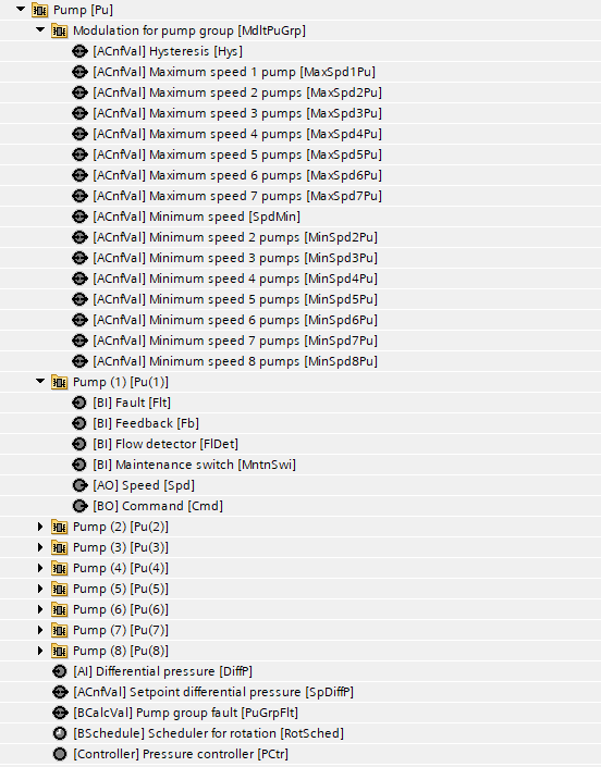
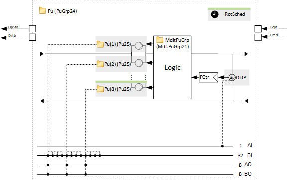
Configurator
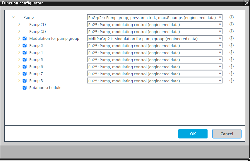

Program blocks are stored in the library without I/Os. Use the auto-create and auto-connect functions to create I/Os and/or to connect them to the interface blocks, e.g., R_A, CMD_B. Alternatively, take the I/Os from the folder containing the predefined I/Os in the library and/or from the plant and connect them to the interface blocks.
Controls a pump group with up to 8 variable speed pumps and performs pressure control.
A program logic (function block ROT_8) measures the operating hours of the pumps and switches on the pump with fewer operating hours when the pump group is switched on. When the next pump is to be switched on, the logic uses these operating hours as a criterion for selecting the next pump.
If one pump has a problem, the program switches on a different pump (if available). If all pumps have a problem, a calculated value object "Pump group fault" generates an alarm.
There is a filter function for the measured value for pressure. However, its time constant is set to a short value, e.g., 1 second. The reason for this is that there is already a pre-filtering with the setting for the COV for the predefined IO, e.g., 5 kPa, and, in addition, the PID controller has a preset neutral zone, e.g., 6 kPa.
PuGrp24 can be used as a pump group of 2 pumps for pressure control with one modulating pump and one backup pump (such as TwnPu24). In this case, the optional pumps and the "Modulation for pump group" must be deleted.
This program block has the following optional functions:
Option: Modulation for pump group
Logic that determines how many pumps are switched on, what their speed is based on, and the number of available pumps and the output signal of the differential pressure controller. There are settings for the minimum and maximum speeds for the relevant pumps which work in parallel.
Use the minimum and maximum speed settings from the data sheet (pressure for given volume flow at a given speed) and adjust them if the pressure setpoint changes.
A parameter in the program defines the number of reserved pumps (default: 0) that are not counted as available pumps and the control signal is not mapped to them.
For example, there is a pump group with 4 pumps and the number of reserved pumps is 1. There are 3 operational pumps and 1 reserved pump. The control signal is mapped to 3 pumps. If all 3 pumps are running and one of them has a fault, the 4th pump jumps in.
Option: Pump 3...Pump 8
The pumps are preset to be of type Pu25. We recommend not changing them to an alternative.
Option: Rotation schedule
A short pulse that forces the net rotation can be set up, e.g., every Tuesday from 5:15 a.m. to 5:16 a.m.
Name | Description | Type | Alarm / Notification class | Trend / Type |
|---|---|---|---|---|
DiffP | Differential pressure | AI: Analog input | No | Yes, 2 |
PCtr | Pressure controller | Ctr: Controller | N/A | N/A |
SpDiffP | Setpoint differential pressure | ACnfVal: Analog configuration value | No | No |
Pu(1) | Pump (1) | N/A | N/A | |
Pu(2) | Pump (2) | N/A | N/A |
Name | Description | Type | Alarm / Notification class | Trend / Type |
|---|---|---|---|---|
MdltPuGrp | Modulation for pump group | N/A | N/A | |
RotSched | Rotation schedule | BSchedule: Binary scheduler | N/A | N/A |
Pu(3) | Pump (3) | N/A | N/A | |
Pu(4) | Pump (4) | N/A | N/A | |
Pu(5) | Pump (5) | N/A | N/A | |
Pu(6) | Pump (6) | N/A | N/A | |
Pu(7) | Pump (7) | N/A | N/A | |
Pu(8) | Pump (8) | N/A | N/A |