[HGen21] Heat generation, cascade control, 2 boilers (burner modulating and 1-stage)
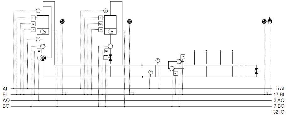
Plant example HGen21 has two boilers, a modulating burner, and a single-stage burner.
Functions
- Collects heat demand and controls to the corresponding setpoint
- Boiler sequence control
- Logic for power control based on a comparison of the setpoint versus actual value on the main flow and delay times
Plant diagram
Components
- One boiler with modulating burner, 1-stage pump, and maintain boiler return with 3-port valve
- One boiler with 1-stage burner, modulating pump, and shutoff valve
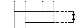
- Bypass between main flow and main return (hydraulic separator)
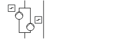
- Main pump group, consumer side
Components and functions
Components and functions of the plant example:
Component | Function | BACnet object |
|---|---|---|
| Fire detection contact Switches the plant off. | [BI] Fire detection contact |
| Operating mode switch Switches the plant to: Auto | Off | On | [MI] Operating mode switch |
| Manual operating mode selection Switches the plant to: Auto | Off | On | [MCnfVal] Manual operating mode selection |
| Present operating mode Reports the present operating mode: Off | On | [MCalcVal] Present operating mode |
| Reason for present operating mode Reports the reason for the present mode: Exception | Operating mode switch | Manual operating mode selection | Heat request | [MCalcVal] Reason for present operating mode |
| Heat request Acquires and evaluates the heat request. | [BCalcVal] Heat request (1) [ACalcVal] Setpoint for heating request (1) [ACnfVal] Offset for setpoint heating request [ACnfVal] Minimum setpoint heating request |
| Main pump group, consumer side Switches on/off one pump each time based on demand. Selects the pump based on pump operating hours. |
> [BO] Command pump 1 > [BO] Command pump 2 |
Reports the fault on the corresponding pump and switches it off. The backup pump is switched on if needed and possible. The plant is switched off if both pumps are in fault. | > [BI] Fault pump 1 > [BI] Fault pump 2 | |
| Hydraulic separator, temperature measurement |
|
Main flow temperature sensor Measures the main flow temperature on the consumer side. | [AI] Main flow temperature consumer side | |
Main return temperature sensor Measures the main return temperature on the generation side. | [AI] Main return temperature generation side | |
| Setpoint determination Calculates the setpoint for the boiler temperature. | [ACalcVal] Present setpoint for main flow temperature [ACnfVal] Delta setpoint for boiler temperature |
| Step up/down Selects the relevant temperature sensor based on the maximum value. Compares the setpoint against the relevant actual value (max selection) and demands more or less power after a delay. |
|
| Power control and compensation Acquires the power demand. Balances power demand by the profile table toward more power (one or more rows down) or less power (one or more rows up). |
|
| Profile table Table of the sequence operation of boilers and their stages. Each row in the table (from top to bottom) supplies more power. Controls the boiler by heat request and predefined sequence. Determines whether to add or switch off a boiler. |
|


 Main pump group (
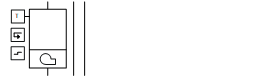
Boiler 1
Component | Function | BACnet object |
|---|---|---|
| Boiler 1 |
|
| Manual switch Switches the boiler to: Auto | Off | On | [MI] Manual switch |
| Boiler temperature and setpoint |
|
Determines the boiler temperature. | [ACalcVal] Present temperature setpoint | |
Sensor for boiler temperature Measures the boiler temperature. | [AI] Temperature | |
| Burner, modulating |
|
Temperature controller Controls the boiler temperature. | > [Controller] Temperature controller | |
Command Switches on/off the burner as needed. | > [BO] Command | |
Modulating control Controls the power between 0 and 100 [%]. | > [AO] Modulating | |
Fault message Reports faults. Switches off the boiler. | > [BI] Fault | |
Monitors the boiler temperature. Switches off the burner. The mixing valve opens to through-port and keeps the boiler pump switched on for two minutes. The valve is then switched to bypass and the pump is switched off. | > [BI] Safety temperature limiter | |
Feedback, binary | > [BI] Feedback | |
| Return temperature sensor Measures the return temperature. | [AI] Return temperature |
| Pump |
|
Command Switches on/off the pump as needed. | > [BO] Command | |
Feedback message Monitors feedback and switches off the boiler. | > [BI] Feedback | |
| Mixing valve Mixes the required amount of water from flow to return to achieve the desired return temperature. |
|
Temperature controller for maintain return temperature Controls the minimum return temperature. | > [Controller] Temperature controller | |
Positioning 0% = Bypass … 100% = Through-port | > [AO] Position | |
Setpoint for maintain return temperature. | [ACnfVal] Setpoint minimum return temperature |





Boiler 2
Component | Function | BACnet object |
|---|---|---|
| Boiler 2 |
|
| Manual switch Switches the boiler to: Auto | Off | On | [MI] Manual switch |
| Boiler temperature and setpoint |
|
Determines the boiler temperature. | [ACalcVal] Present temperature setpoint | |
Sensor for boiler temperature Measures the boiler temperature. | [AI] Temperature | |
| Burner, 1-stage |
|
Temperature controller Controls the boiler temperature. |
| |
Command Switches on/off the burner as needed. | > [BO] Command | |
Fault message Reports faults. Switches off the boiler. | > [BI] Fault | |
Monitors the boiler temperature. Switches the burner off and keeps the shutoff valve open and the boiler pump on for two minutes. The shutoff valve is then closed and the pump switched off. | > [BI] Safety temperature limiter | |
Feedback, binary | > [BI] Feedback | |
| Pump |
|
Temperature controller Controls the boiler temperature. | > [Controller] Temperature controller | |
Command Switches on/off the pump as needed. | > [BO] Command | |
Modulating control Reduces the water flow through the boiler if the setpoint for boiler temperature can no longer be achieved with the burner. | > [AO] Modulating | |
Feedback message Monitors feedback and switches off the boiler. | > [BI] Feedback | |
| Shutoff valve Locks/unlocks the boiler return. |
|
Command Closes or opens the boiler circuit (2): Close | Open | > [BO] Command |





Overview
The following diagram is a simplified illustration of plant example HGen21.
Sequencing energy generators
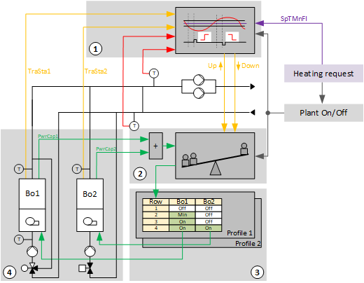
Key
1, 2 |
|
SpTMnFl | Setpoint for main flow temperature |
3 |
|
Bo1 | Boiler 1 |
Bo2 | Boiler 2 |
4 |
|
PwrCap1 | Available power 1 |
PwrCap2 | Available power 2 |
TraSta1 | Transient state 1 |
TraSta2 | Transient state 2 |
Step up/down (1)
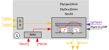
Key
DlyUp | Delay for an up impulse |
DlyDn | Delay for a down impulse |
Nz | Neutral zone |
SpTMnFl | Setpoint for main flow temperature |
TMnFl | Temperature in the main flow after the hydraulic separator (consumer side) |
TMnRt | Temperature in the main return prior to the hydraulic separator (generator side) |
TraSta1 | Transient state 1 |
TraSta2 | Transient state 2 |
Important settings:
- Neutral zone (Nz) = 3 K
- Delay for up impulse (DlyUp) = 10 min
- Delay for down impulse (DlyUp) = 10 min
If the function is enabled, the higher value of the two temperatures in main flow 'TMnFl' and main return 'TMnRt' is selected as the controlled variable. If the measured temperature exits the neutral zone 'Nz' by setpoint 'SpT', an impulse "Step up" or "Step down" is sent over output 'StepUp' or 'StepDn' to power balance. The impulse is sent with a delay. The delays are determined using the settings 'DlyUp' and 'DlyDn'.
There are two cases:
- One or both temperatures drop. Pulse "Step up" is generated.
Heat generation supplies too little power and/or flow in the consumer circuit is higher than in the generation circuit. - One or both temperatures increase. Pulse "Step down" is generated.
Heat generation supplies too much power and/or flow in the consumer circuit is lower than in the generation circuit.
To prevent continued switching prematurely, the evaluation logic is held after each impulse. The enabled heat generator returns its 'TraSta' to "Step up/down". The evaluation logic restarts once the transition state expires.
Step up or step down
Power control and compensation (2)
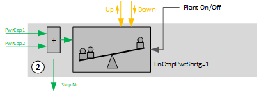
Key
EnCmpPweShrtg | Automatic power compensation for a loss of power |
PwrCap1 | Available power 1 |
PwrCap2 | Available power 2 |
Important settings:
- Automatic power control and compensation for a loss of power (EnCmpPwrShrtg) = 1 (see below)
Power control and compensation receive the request from "Step up/down" for more or less power as a result of the pulse "Step up" or "Step down". In this way, Power control and compensation" triggers a change to the following or previous line in the profile table.
"Power control and compensation" then checks whether the change in row in the "profile table" resulted in the desired increase or reduction to the currently produced output. It receives the feedback on input [PwrCap] on the power currently produced and compares it against the value in internal memory [PrPwrCap].
In the event that the desired result does not arrive, "Power control and compensation" changes the row until the desired increase or reduction to current power is reached.
Automatic power compensation in the event of a power shortage [EnCmpPwrShrtg]: Power shortage is detected based on input [PwrCap] and balanced by sequential steps, e.g. due to a loss of a heat generator due to a fault.
Power control and compensation
Profile table (3)
In the profile table, the sequence is determined for switching on the heat generators. Four different profiles can be created. The entries are entered in each profile so that total power of the enabled heat generators or stages increases as the row number increases.
Function block SELP_8MS determines the profile table.
[SELP_8MS] Profile and table value selection for 8 multistate values
Two profiles are prepared in the example:
Profile 1: "Winter profile"
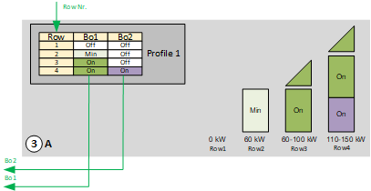
Boiler 1 (100 KW) is a modulating boiler and is intended as the main boiler for winter operation.
Boiler 2 is switched on if:
- The power for boiler 1 is not sufficient
- Boiler 1 is in fault
Profile 2: "Summer profile"
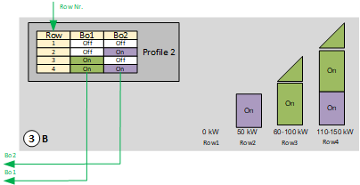
Boiler 2 (50 KW) is intended as the boiler for summer operation.
It switches to boiler 1 if:
- The power for boiler 2 is not sufficient
- Boiler 2 is in fault
In the example, a parameter block is planned for the changeover of profile. A logic can be programmed for the specific project.
Profile table
Heat generator (Boiler 1 and 2) (4)
The heat generators enabled by the profile table report on available power [PwrCap] to power control and compensation.
They also report in the event of an active change of the power stage, the transient state [TraSta] to "Step up/down". No further "Step up" or "Step down" is triggered during an active transient state.
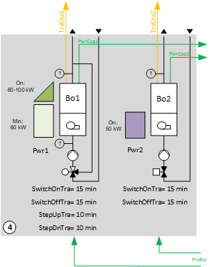
Key
TraSta1 | Transient state 1 |
TraSta2 | Transient state 2 |
PwrCap1 | Available power 1 |
PwrCap2 | Available power 2 |
Bo1 | Boiler 1 |
Bo2 | Boiler 2 |
SwiOnTra | Transient state at switch-on |
SwiOffTra | Transient state at switch-off |
StepUpTra | Transient state when stepping up a stage |
StepDnTra | Transient state when stepping down a stage |
Boiler 1 with modulating burner, 1-stage pump, maintain boiler return with 3-port valve
Operating modes: Off, On, Min.
Settings for power feedback:
Complete the power per stage on function block SELMS_R
1 Off = 0 KW
2 On = 100 KW
3 Min. = 60 KW
Settings for feedback of the transient state on the nested chart BoTraSta(1):
Components, sequence, and function in CMDSEQ_B (Bo1)
Plant operating mode | Component | ||
|---|---|---|---|
| Pu | Vlv | Bu |
Off | Off | Off | Off |
On | On | On | On |
Min | On | On | On |
| |||
Sequences |
| ||
Start sequence | 1 | 2 | 2 |
Start function | Feedback | AND (Group with next aggregate) | AND (Group with next aggregate) |
Start delay | - | - | - |
| |||
Stop sequence | 2 | 2 | 1 |
Stop function | AND (Group with next aggregate) | AND (Group with next aggregate) | Delay |
Stop delay | - | - | 2m |
[CMDSEQ_B] Command sequence for binary
Start sequence
- The pump switches on. It is further switched if an operating message comes from the pump on the input pin for CmdSeq(Bo1).
- Control of maintain return with the valve and the burner switches on simultaneously (function AND).
Stop sequence
- The burner switches off. It waits for 2 minutes (function Delay).
- The valve is set to bypass and the pump switches off (function AND).
Boiler 2 with 1-stage burner, modulating pump, and shutoff valve
Operating modes: Off, On
Settings for power feedback:
Complete the power per stage on function block SELMS_R
1 Off = 0 KW
2 On = 50 KW
Settings for feedback of the transient state on the nested chart BoTraSta(2):
SwiOnTra | Transient state at switch-on | 15 min |
SwiOffTra | Transient state at switch-off | 15 min |
Components, sequence, and function in CMDSEQ_B (Bo2)
Plant operating mode | Component | ||
|---|---|---|---|
| Vlv | Pu | Bu |
Off | Off | Off | Off |
On | On | On | On |
| |||
Sequences |
| ||
Start sequence | 1 | 2 | 3 |
Start function | Delay | Feedback | AND (Group with next aggregate) |
Start delay | 30 s | - | - |
| |||
Stop sequence | 2 | 2 | 1 |
Stop function | AND (Group with next aggregate) | AND (Group with next aggregate) | Delay |
Stop delay | - | - | 2m |
Start sequence
- The shutoff valve opens. It is further switched after 30 seconds.
- The pump switches on and its control is enabled. It is further switched if an operating message comes from the pump on the input pin for CMDSEQ_B (Bo2).
- The burner switches on.
Stop sequence
- The burner switches off. It waits for 2 minutes (function Delay).
- The shutoff damper closes and the pump switches off (function AND).
Setpoint generation
Main pump group, consumer side
The example implements two main pumps, each with a fault message.
The changeover occurs:
- Every 168 hours regardless of operating hours
- Regardless of fault
The changeover is implemented with function block ROT_8.
[ROT_8] Rotation switch with 8 outputs
Setpoint generation and temperature control
Individual heat consumption transmits its heat request and forms the temperature setpoint for main flow as per this heat request. The setpoint is increased slightly and sent to the heat generators.
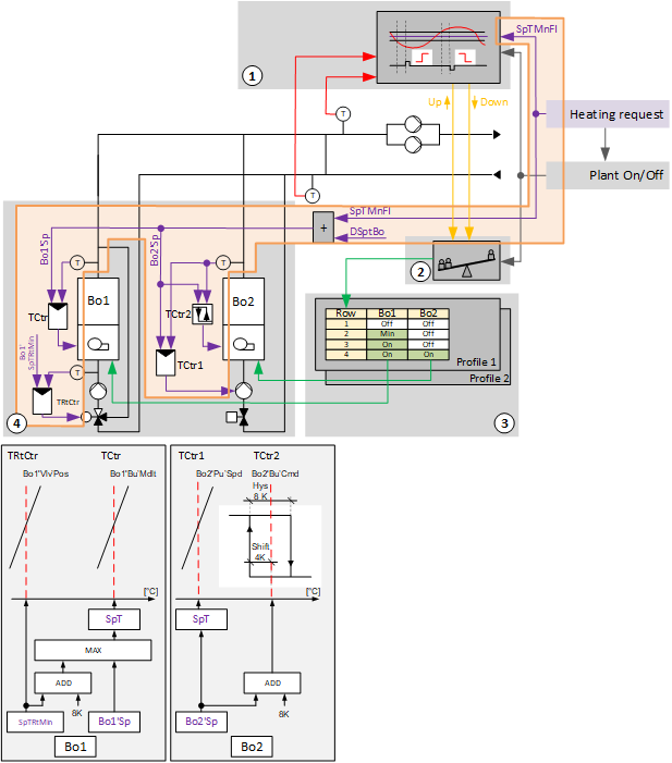
Key
1, 2 |
|
SpTMnFl | Setpoint for main flow temperature |
DSpTBo | Delta setpoint for boiler temperature |
3 |
|
Bo1 | Boiler 1 |
Bo2 | Boiler 2 |
4 |
|
Bo1'Sp | Setpoint for boiler 1 |
Bo2'Sp | Setpoint for boiler 2 |
TCtr | Temperature controller |
TRtCtr | Return temperature controller |
Bo1'VlVPos | Boiler 1 valve position |
Bo1'Bu'Mdlt | Boiler 1 burner modulating control |
Bo2Pu'Spd | Boiler 2 pump speed |
Bo2Bu'Cmd | Boiler 2 burner command |
Hys | Hysteresis |
SpT | Temperature setpoint |
SpTRtMin | Setpoint minimum return temperature |
BACnet objects for boiler 1
Name | Description | Object type | Default value |
|---|---|---|---|
Bo1'Vlv'TCtr | Temperature controller maintain return valve boiler 1 Controls the boiler return temperature. | Controller | N/A |
The temperature controller acts as a PI controller (PID with derivative action time Tv=0) and compares the minimum return temperature setpoint [Bo1'SpTRtMin] against the return temperature [Bo1'TRt] and calculates the valve position [Bo1'Vlv'Pos] on the output. The following controller variables are preset: | |||
Bo1'Vlv'TCtr | Temperature controller burner boiler 1 Controls the boiler temperature. | Controller | N/A |
The temperature controller acts as a PI controller (PID with derivate action time Tv=0) and compares the temperature setpoint [Bo1'PrSpT] against the boiler temperature [Bo1'T] and calculates the modulating control for the burner [Bo1'Bu'Mdlt] on the output. The following controller variables are preset: | |||

The setpoint for return temperature may not be exceeded and is specified by the boiler manufacturer. The setpoint for boiler temperature is derived from this setpoint. The setpoint for boiler temperature is limited to the minimum to a value derived from the setpoint for return temperature plus a difference of, e.g. 8K.
BACnet objects for boiler 2
Name | Description | Object type | Default value |
|---|---|---|---|
Bo2'Pu'TCtr | Temperature controller pump boiler 2 Controls the boiler temperature. | Controller | N/A |
The temperature controller acts as a PI controller and compares the temperature setpoint [Bo2'PrSpT] against the boiler temperature [Bo2'T] and calculates the modulating control for the pump [Bo2'Pu'Mdlt] on the output. The following controller variables are preset: | |||
Plant operating modes:
- Off (1)
- On (2)
The operating modes are reported on [MCalcVal] object 'Present operating mode'.
At the same time, the reason for the present operating mode is reported to another [MCalcVal] object:
- Exception (1)
- Operating mode switch (2), resulting from an active (not equal to Auto) operating mode switch
- Operating mode (3), resulting from an active (not equal to Auto) manual operating mode selection
- Heat request (4)
There is a normal mode and exception mode.
Normal mode
Sources for normal mode:
- [MI] Operating mode switch
- [MCnfVal] Manual operating mode selection
- [HReq (1)] Heat request
In normal operation, operating mode 'On', the main pumps are switched on and the logic for boiler sequence operation (step up/down, power control and compensation and profile table) is enabled. The logic for boiler sequence operation controls the individual energy generators using their function blocks CMDSEQ_B.
[CMDSEQ_B] Command sequence for binary
Exception mode
Sources for exception mode:
- Fire detection contact
- Faults to both pumps in the main pump group
- Fault to both boilers
In exception mode, all outputs are switched off directly at priority 5 and the present operating mode is set to 'Off'.
It is reported on input [RpdOff] from all CMDSEQ_B on the energy generators.
Start-up control (nested chart SttUpAlmHdl)
The following functionality is available for an automatic startup of the plant, e.g. after a loss of power and return of power:
- Fixed switch-on delay (can be set on input pin [DlySttUp])
- The plant remains off to ensure communications are reliable and cross-check references are triggered. 'Exception' is reported as the reason for the present operating mode.
- Automatic acknowledge (2x) of possible pending alarms during a fixed switch-on delay.
- Additional adjustable delay for staged plant ramp-up (can be set on input pin [DlyOn])
Alarm handling (nested chart SttUpAlmHdl)
The state of events on the plant is acquired by BACnet object 'Plant state'. The state is mapped on function block CMN_EVT.
[CMN_EVT] Common event
The following functions are available:
- Automatic acknowledge (2x) after startup
- Alarm acknowledgement with a value object
- Alarm indication:
- For pending alarms On
- For unprocessed alarms flashing - Ability to connect the acknowledge button [BI]
- Ability to connect to an alarm indication [BO], e.g. an alarm lamp through an output block [BO]
- Ability to connect to other alarm handling functions on other plants, e.g. acknowledge button and alarm indication for multiple plants in the same control cabinet
Name | Description | Type | Signal/connection | State text | Engineering unit |
|---|---|---|---|---|---|
FireDetCont | Fire detection contact Alarm function: Extended (Notification class 7) Reference value: Tripped Time deviation: 0 [s] | BI | NC contact | Normal | Tripped | N/A |
OpModSwi | Operating mode switch | MI | N/A | Auto | Off | On | N/A |
FltPu (1) | Fault pump (1) Alarm function: Extended (Notification class 7) Reference value: Tripped Time deviation: 0 [s] | BI | NO contact | Normal | Tripped | N/A |
FltPu (2) | Fault pump (2) Alarm function: Extended (Notification class 7) Reference value: Tripped Time deviation: 0 [s] | BI | NO contact | Normal | Tripped | N/A |
CmdPu (1) | Command pump (1) | BO | NO contact | Off | On | N/A |
CmdPu (2) | Command pump (2) | BO | NO contact | Off | On | N/A |
TMnFlCns | Main flow temperature consumer side | AI | LG-Ni1000 | N/A | 0...100 [°C] |
TMnRtGen | Main return temperature generation side | AI | LG-Ni1000 | N/A | 0...100 [°C] |
Bo1'ManSwi | Boiler 1 manual switch | MI | N/A | Auto | Off | On | N/A |
Bo1'T | Boiler 1 temperature | AI | LG-Ni1000 | N/A | 0...100 [°C] |
Bo1'TRt | Boiler 1 return temperature | AI | LG-Ni1000 | N/A | 0...100 [°C] |
Bo1'Bu'Flt | Boiler 1 burner fault Alarm function: Basic (Notification class 8) Reference value: Tripped Time deviation: 0 [s] | BI | NC contact | Normal | Tripped | N/A |
Bo1'Bu'SftyTLm | Boiler 1 burner safety temperature limiter Alarm function: Basic (Notification class 8) Reference value: Tripped Time deviation: 0 [s] | BI | NO contact | Normal | Tripped | N/A |
Bo1'Bu'Fb | Boiler 1 burner feedback | BI | NO contact | Off | On | N/A |
Bo1'Bu'Mdlt | Boiler 1 burner modulating control | AO | 0...10V | N/A | 0...100 [%] |
Bo1'Bu'Cmd | Boiler 1 burner command | BO | NO contact | Off | On | N/A |
Bo1'Pu'Cmd | Boiler 1 pump command Alarm function: Extended (Notification class 7) Reference value: Bo1'Pu'Fb Time deviation: 30 [s] | BO | NO contact | Off | On | N/A |
Bo1'Pu'Fb | Boiler 1 pump feedback | BI | NO contact | Off | On | N/A |
Bo1'Vlv'Pos | Boiler 1 valve position | AO | 0...10V | N/A | 0...100 [%] |
Bo2'ManSwi | Boiler 2 manual switch | MI | N/A | Auto | Off | On | N/A |
Bo2'T | Boiler 2 temperature | AI | LG-Ni1000 | N/A | 0...100 [°C] |
Bo2'Bu'Flt | Boiler 2 burner fault Alarm function: Basic (Notification class 8) Reference value: Tripped Time deviation: 0 [s] | BI | NC contact | Normal | Tripped | N/A |
Bo2'Bu'StfyTLm | Boiler 2 burner safety temperature limiter Alarm function: Basic (Notification class 8) Reference value: Tripped Time deviation: 0 [s] | BI | NO contact | Normal | Tripped | N/A |
Bo2'Bu'Fb | Boiler 2 burner feedback | BI | NO contact | Off | On | N/A |
Bo2'Bu'Cmd | Boiler 2 burner command | BO | NO contact | Off | On | N/A |
Bo2'Pu'Cmd | Boiler 2 pump command Alarm function: Extended (Notification class 7) Reference value: Bo2'Pu'Fb Time deviation: 30 [s] | BO | NO contact | Off | On | N/A |
Bo2'Pu'Fb | Boiler 2 pump feedback | BI | NO contact | Off | On | N/A |
Bo2'Pu'Mdlt | Boiler 2 pump modulating control | AO | 0...10V | N/A | 0...100 [%] |
Bo2'Vlv'Cmd | Boiler 2 valve command | BO | NO contact | Close | Open | N/A |