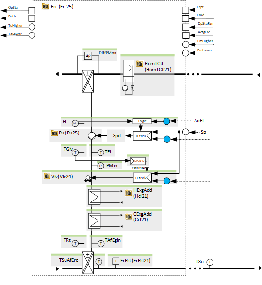
[Erc25] Run-around coil, temperature-controlled with heat and cool exchanger
Program block, name / node subtype: [Erc25] Run-around coil, temperature-controlled with heat and cool exchanger
Library hierarchy: Ventilation and air conditioning equipment
Family: Erc
Project tree | Diagram |
|---|---|
|
|
|
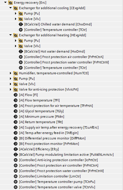
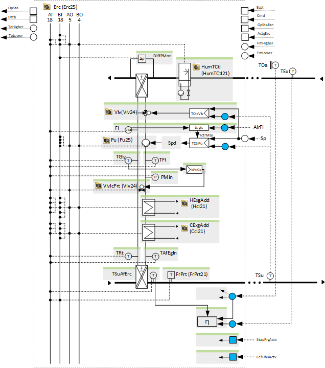
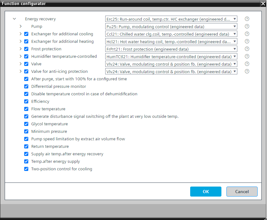
Configurator

Program blocks are stored in the library without I/Os. Use the auto-create and auto-connect functions to create I/Os and/or to connect them to the interface blocks, e.g., R_A, CMD_B. Alternatively, take the I/Os from the folder containing the predefined I/Os in the library and/or from the plant and connect them to the interface blocks.
Controls the supply air temperature (heating and cooling) by changing the:
- pump speed of a variable speed pump
- valve position of an optional bypass valve
- output power of optional heat exchangers for additional heating and cooling
- output power of a humidifier for adiabatic cooling of the extract air
Some temperature controllers (the controllers for the pump and the optional valve) change their control action dynamically for heating or cooling based on conditions from another program block.
The minimum and maximum pump speed can be parameterized in the program. The maximum pump speed can be defined by an optional logic for its limitation following the extract air volume flow.
There are several temperature controllers that are in sequence:
- A temperature controller in the optional exchanger for additional heating
- A temperature controller for the pump
- A temperature controller for the optional valve
- A temperature controller in the optional humidifier for adiabatic cooling
- A temperature controller in the optional exchanger for additional cooling
Sequence for heating
The temperature controller for the valve increases its output and closes the bypass valve while the pump runs at minimum speed. When the temperature controller for the valve reaches its maximum (bypass valve is closed), the temperature controller for the pump takes over and increases the pump speed to the maximum pump speed. When the temperature controller for the pump reaches its maximum, the temperature controller in the exchanger for additional heating takes over.
Sequence for cooling
The temperature controller for the valve is set at its maximum and the temperature controller for the pump takes over. The temperature controller for the pump either goes to its maximum if the option "Two-position control for cooling" is active, or continuously increases the pump speed to its maximum. When the temperature controller for the pump reaches its maximum, the temperature controller in the humidifier for adiabatic cooling takes over. When it reaches its maximum, the temperature controller in the exchanger for additional cooling takes over.
This program block has the following optional functions:
Option: Exchanger for additional cooling (1xBO, 1xAO, 4xBI, 3xAI)
Controls a cooling exchanger that feeds in additional cooling energy and is part of the temperature control sequence for the supply air (Ccl21).
We do not recommend any other alternatives except Ccl21.
Option: Exchanger for additional heating (1xBO, 1xAO, 5xBI, 4xAI)
Controls a heat exchanger that feeds in additional heating energy and is part of the temperature control sequence for the supply air (Hcl21).
We do not recommend any other alternatives except Hcl21.
Option: Frost protection (1xBI, 1xAI)
Performs frost protection (FrPrt21).
The Energy recovery and the "Exchanger for additional heating" both have the optional chart "Frost protection".
For the "Frost protection" in the Energy recovery: Delete the option "Frost protection water controller".
For the "Frost protection" in the "Exchanger for additional heating": Keep the option "Frost protection water controller" if there is a return temperature. "Frost protection" and "Frost protection air controller" can be kept and connected to the corresponding I/Os, "FrPrtMon" and "TFrPrtA", in the Energy recovery.
Option: Humidifier temperature-controlled (1xBO, 1xAO, 3xBI, 2xAI)
Controls a humidifier for adiabatic cooling of the extract air and is part of the control sequence for the supply air (HumTCtl21).
Option: Valve (1xAO, 1xAI)
Controls the position of a bypass valve that increases or reduces the power of the energy recovery (Vlv24).
Option: Valve for anti-icing protection (1xAO, 1xAI)
Controls the position of a valve that supports the anti-icing protection (Vlv24).
If there is only 1 valve, there are 2 possibilities:
1. The valve supports anti-acing protection. The valve is not part of the temperature control sequence. This is a 2-way valve in the bypass after the pump with small dimension.
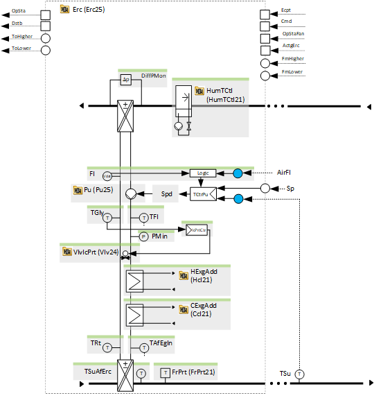
2. The valve supports anti-acing protection. The valve is part of the temperature control sequence. This is likely a valve in the bypass after the pump or a 3-way valve (with Sel(VlvType).K=1 manually set.
Option: After purge, start with 100 % for a configured time
Provides an interface to the state of the "Start-up purge" function and logic to keep the energy recovery at 100 % for a configurable time, e.g., 4 minutes, after the "Start-up purge" function has finished.
Option: Differential pressure monitor (1xBI)
Reads the signal from a differential pressure monitor over the energy recovery. If the differential pressure increases due to ice forming on the surface of the energy recovery aggregate, it reduces the output of the temperature controller for the valve to perform anti-icing protection.
Option: Disable temperature control in case of dehumidification
Provides an interface (most likely to the cooling coil) and logic to disable the temperature control in case of dehumidification to not preheat the air when the cooling coil performs dehumidification.
If the energy recovery is set for cooling, it runs at 100 %.
Option: Efficiency
Calculates the efficiency of the energy recovery. The function block MON_ERC is used in the program.
This efficiency calculation needs the option "Supply air temperature after energy recovery".
Option: Flow temperature (1xAI)
Reads the signal from a flow temperature sensor.
Option: Generate disturbance signal switching off the plant at very low outside temperature
If there is a problem with the energy recovery at very low outside temperature, the heating power may be insufficient, and the resulting supply air temperature may drop to a level that is above the frost protection, but still very uncomfortable. This is why a disturbance signal that shuts down the air handling unit plant is generated.
Option: Glycol temperature (1xAI)
Reads the signal from the glycol temperature sensor and performs anti-icing protection with a PID controller that limits the output of the temperature controller to the valve and continuously opens the bypass.
Option Minimum pressure (1xAI)
Reads the signal from a pressure sensor in the glycol circuit and generates an alarm if the pressure is too low.
Option: Pump speed limitation by extract air volume flow
Calculates an optimal maximum pump speed depending on the air volume flow.
To achieve an optimal energy recovery efficiency, the criteria defined by the following equation must be met:
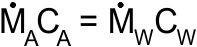
Heat capacity of the air = Heat capacity of the heat transfer media
 = Mass flow air
 = Specific heat capacity of air
 = Mass flow heat transfer medium
 = Specific heat capacity of heat transfer medium
During the commissioning, the relationship between Ṁw and the pump speed can be measured. Based on this, the relationship between the mass flow air and the pump speed is calculated and set up in the program (CHAR_LIN). This helps to keep the mass flow of the heat transfer medium at the optimum level and prevents it from being unnecessarily high.
If the pump speed is not limited, there is likely a range, e.g., 70-100 %, where the output of the temperature controller increases while the power of the energy recovery does not increase. The temperature controller keeps the token until the maximum output is reached. The maximum output is not limited by the comparison of the heat capacities. It takes longer for the next aggregate in the temperature control sequence to be released for control and the total power output increases again.
Option: Return temperature (1xAI)
Reads the signal from a flow temperature sensor.
Option: Supply air temperature after energy recovery (1xAI)
Reads the signal from a supply air temperature sensor after energy recovery.
This is an important sensor for calculating the utilization rate of the energy recovery with ErcUtzRate21.
Option: Temperature after energy supply (1xAI)
Reads the signal from a temperature sensor after the exchangers for additional heating and cooling.
Option: Two-position control for cooling
2-position control mode for the temperature controller in case of cooling.
Name | Description | Type | Alarm / Notification class | Trend / Type |
|---|---|---|---|---|
Pu | Pump | N/A | N/A | |
TCtrPu | Temperature controller pump | Ctr: Controller | N/A | N/A |
Name | Description | Type | Alarm / Notification class | Trend / Type |
|---|---|---|---|---|
|
Vlv | Valve | N/A | N/A | |
Further elements that belong to this element: TCtrVlv | Temperature controller valve | Ctr: Controller | ||||
HExgAdd | Exchanger for additional heating | N/A | N/A | |
CExgAdd | Exchanger for additional cooling | N/A | N/A | |
TGly
| Glycol temperature | AI: Analog input | No | Yes, 2 |
Further elements that belong to this element: IcPrtCtr | Anti-icing protection controller | Ctr: Controller | ||||
VlvIcPrt | Valve for anti-icing protection | N/A | N/A | |
DiffPMon | Differential pressure monitor | BI: Binary input | Yes, 8 | No |
TSuAfErc | Supply air temperature after energy recovery | AI: Analog input | No | Yes, 2 |
Efcy | Efficiency | ACalcVal: Analog calculated value | No | No |
FrPrt | Frost protection | N/A | N/A | |
TAfEgIn | Temperature after energy supply | AI: Analog input | Yes, 4 | Yes, 2 |
TFl | Flow temperature | AI: Analog input | Yes, 4 | Yes, 2 |
TRt | Return temperature | AI: Analog input | Yes, 4 | Yes, 2 |
PMin | Minimum pressure | AI: Analog input | Yes, 4 | Yes, 3 |
Description |
|---|
|
2-position control for cooling |
After purge start with 100 % for a configured time. |
Generate disturbance signal that switches off the plant at very low outside temperature. |
Disable temperature control in case of dehumidification |
Pump speed limitation by extract air volume flow Fl | Flow | AI: Analog input LmCtr | Limitation controller | Ctr: Controller Element that belongs to the further options: PuMdltLmActv | Pump modulating limitation active | BCalcVal: Binary calculated value |