I/O configuration
To open the I/O configuration task select Building > Building structure and double-click a bus interface module.
Use the I/O configuration task to add TX-I/O devices to the bus interface module and configure signal types, and their properties.
Basic engineering workflow
Device list
1 | Task selector | 2 | Plants navigation view |
3 | Toolbar | 4 | I/O Configuration area |
5 | Library and Properties |
| |
① Task selector
Task | Description |
|---|---|
I/O configuration | |
Modbus | |
M-bus | |
KNX PL-Link | |
BACnet references | |
BACnet objects | |
Programming |
② Plants navigation view
Displays the created I/Os.
Command | Description |
|---|---|
| Open/close folder structure. |
| Hide/unhide plant information. |
Add data point | Opens the Add data point dialog box where you can create a new data point. Plant must be selected to activate the functionality. |
Assign all | Automatically assigns all created I/Os to the terminals of a TX module. |
| Plant focus is set for automatic drop destination. In the Graphical view or Tabular view newly added objects from the library to an I/O module are assigned to this plant. |
| Plant focus is not set for automatic drop destination. Objects can be assigned to the plant or lower level by using drag & drop at any time. |


Make sure that there are no unassigned I/Os left over since all I/O are loaded into the bus interface module. Unassigned I/Os can create configuration errors in the device.
③ Toolbar
Command | Description |
|---|---|
|
State | Indicates the state of the application. The green color indicates that the application is online and running or paused.
|
Check | Checks for duplicate names, number of I/Os, trend limits, etc. The check is automatically performed before loading a device. |
(Play) | Only visible when the device is online. Activates an online session and loads changes for the selected device. |
(Pause) | Only visible when the device is online and an online, session is started. Deactivates an active online session. |
(Alarming) | Temporarily suppresses all alarms for testing purposes. Note: If several alarms are triggered due to a field device status is “Device-Missing” (perform an alarm shower), only the “Device-Missing” alarm is sent to the corresponding recipients. This ensures that the user does not receive and have to acknowledge multiple alarms. |
Example of an activated online session
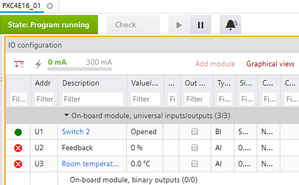
④ I/O Configuration area
Contains the following elements.
- Tools such as the estimated power consumption bar
- Module assignment table (Tabular view)
- TX-I/O graphical view with drag functionality
Element | Description |
|---|---|
| Expand/collapse all extension modules. |
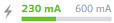
| Estimated power consumption bar. Shows a bar of the actual power consumption compared to the maximum possible consumption. Note: When calculating the required amount of power, total consumption is always estimated. After assigning the effective data points/signal type, the required power consumption may be reduced. |
Add module | Opens the Add module dialog box. Select the type and the address of the TX module. |
Tabular view/Graphical view | You can toggle between Tabular view tab and Graphical view tab. |


The module assignment table displays the TX-I/O modules with the assigned I/Os. Click Add module to open a list of available modules and accessories.
In Graphical view you can drag data points to the device and to I/O modules.
TX-I/O rail engineering
⑤ Library and Properties
The Library and Properties area on the right can be toggled. The Library view contains elements which can be dragged directly to the working area.
Library
The Property view shows the properties of the selected element. The items displayed in the Property view depend on the selected object type.
You can also set the Signal type in the Property view. But make sure the signal type is supported by the module, otherwise the I/O will be unassigned from the module.