M-bus
The M-bus (Meter Bus) was designed to enable remote reading of utility meters, for example, heat cost allocation devices, heat-, water-, gas- meters and with some restrictions also electricity meters and heating controllers. The main application purpose of M-bus systems is to read out a complete and consistent set of metering data from the connected meters for billing and visualization/diagnostics purposes. The M-bus manager data acquisition acts as client and the subordinates act as servers to exchange messages in a request-response messaging pattern.
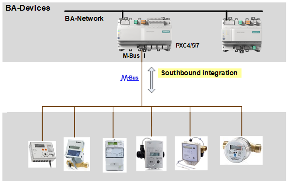

The M-bus manager implementation of the PXC4/5/7 device will be restricted to few basic and common protocol features. The PXC4/5/7 device will not make use of all other special features, options and variants of the M-bus specification, since the support and interpretation of these protocol mechanisms are manufacturer specific.
More information can be found in the M-bus expert documentation A6V16039082 on SID.
The M-bus task allows you to create a network topology and integrate networked field devices for measurement. You can add networks, devices and data points.
1 | Task selector | 2 | Plants navigation view |
3 | Toolbar | 4 | M-bus area |
5 | Library and Properties |
|
|
① Task selector
Task | Description |
|---|---|
I/O configuration | |
Modbus | |
M-bus | |
KNX PL-Link | |
BACnet references | |
BACnet objects | |
Programming |
② Plants navigation view
The Plants navigation view shows the hierarchy of devices in the plant. Select and right-click the plant to display the context menu commands.
Context menu command | Description |
|---|---|
| Open/close folder structure. |
| Hide/unhide plant information. |
Filter | Enter letters to reduce the object view. |
Add plant | Opens the Add plant window for creating a new plant. |
Add folder | Opens the Add folder window for creating a new folder. |
Delete | Deletes the selected element. |
Duplicate | Creates a copy of the selected element. |
Rename | Opens the Rename… window for entering a different name for the selected element. |
Show in program | Opens the selected element in the Programming editor. |
Open properties | Opens the Properties of the selected element. |


③Toolbar
Command | Description |
|---|---|
State | Indicates the state of the application. The green color indicates that the application is online and running or paused.
|
Check | Checks for duplicate names, number of I/Os, trend limits, etc. The check is performed automatically before loading a device. |
(Play) | Only visible when the device is online. Activates an online session and loads changes for the selected device. |
(Pause) | Only visible when the device is online and an online, session is started. Deactivates an active online session. |
(Alarming) | Temporarily suppresses all alarms for testing purposes. Note: If several alarms are triggered due to a field device status is “Device-Missing” (perform an alarm shower), only the “Device-Missing” alarm is sent to the corresponding recipients. This ensures that the user does not receive and have to acknowledge multiple alarms. |
 , the serial number is not visible after a delta download. Therefore, a full download is required to make the serial number visible.
④ M-bus area
In the middle M-bus area, there is a tree to navigate through the elements of the M-bus network.
Command | Description |
|---|---|
Expand/Contract all button | Expand or contracts the whole M-bus tree. |
Hide network | Hides the network tree. |
Add network | Opens the Add network dialog box where you can create a new network. |
Add device | Opens the Add device dialog box where you can create a new device. |
Add data point | Opens the Add data point dialog box where you can create a new data point. |
Property table
The property table provides an overview of the M-bus network. There are different columns depending on your selection.
If you select the Networks in offline mode, you can see the following elements in the workplace table:
Column | Description |
|---|---|
Description | Description of the M-bus network. |
Port | Virtual property. Current port to which the network is assigned. |
Max. baud rate | Maximum baud rate. |
Name | Network object Name. |
If you select the M-bus device in offline mode, you can see the following elements in the workplace table:
Column | Description |
|---|---|
Description | The description of the device. |
Secondary address | Serial-Number property. |
Primary address | Network-address property. |
Baud rate | Enumeration selected via drop down menu. Default: Auto |
Polling time | Enumeration selected via drop down menu. Default: T2. |
Device type | Field device type property. There are 2 choices "M-bus device"(default), "M-bus level converter" |
Name | Network object name. Name is shown from pant level. |
If you select the M-bus data point in offline mode, you can see the following elements in the workplace table:
Column | Description |
|---|---|
Description | Description of the data point. |
Unit | Displays the BACnet object units. |
Type | Displays the BACnet object type. |
Measured value | Shows the current value of the preset used for the data point or custom if one cannot be found. Clicking it, opens a drop down menu with all available values for the given data type. |
Data type | Data type property of an object. Grayed out if property not available on object type. |
Function code | Shows the current value of function code. |
Address | The port address within the M-bus network. Editable numeric field. |
(Alarming) | A checkbox allows to enable/disable the intrinsic alarm extension of the BACnet object. Select to activate the alarming function for the object. Note: If several alarms are triggered by the same object (performs an alarm shower), only one alarm is sent to the corresponding recipients. This ensures that the user does not receive and have to acknowledge multiple alarms. |
(Trending) | A checkbox allows to create/delete a trend log for an IO. Created trend log is automatically linked to the current value of the IO. Select to activate the trending function for the object. |
Name | Data point object Name. Name is shown from plant level. |
⑤ Library and Properties
The Library and Properties area on the right have an option of toggle. The Library view contains elements which can be dragged directly to the working area.
Library
The Property view shows the properties of the selected element. The items displayed in the Property view depend on the selected object type.
Context menu
M-bus editor context menu
Command | M-bus Offline | M-bus Online | Description | |
|---|---|---|---|---|
Networks | Add network | Yes | No | Opens the Add network dialog box to add a network. |
Network | Add device | Yes | No | Opens the Add device dialog box to add an M-bus device. |
Delete | Yes | No | Deletes the selected object. | |
Rename | Yes | No | Opens the Rename device dialog box where you can change the name and description of the selected object. | |
Acknowledge alarm | No | Yes | Acknowledges the alarm state. | |
Start tracing | No | Yes | Opens the Traces –Network view window where you can view transmitted and received M-bus telegrams with date and time stamp. Available only for a single device or the whole network. | |
Import | Yes | No | Opens a local path in the user's PC to import a .csv file. | |
Show in program | Yes | Yes | Opens the Programming editor. | |
Open properties | Yes | Yes | Opens the properties of the selected object. | |
Device | Add data point | Yes | No | Opens the Add data point dialog box where you can create a new data point. |
Delete | Yes | No | Deletes the selected object. | |
Duplicate | Yes | No | Creates a copy of the selected object. | |
Rename | Yes | No | Opens the Rename device dialog box where you can change the name and description of the selected object. | |
Unassign | No | Yes | Removes the assigned device to the M-bus network. | |
Acknowledge alarm | No | Yes | Acknowledges the alarm state. | |
Start tracing | No | Yes | Only available when online. Opens the Traces –Network view window where you can view transmitted and received M-bus telegrams with date and time stamp. Available only for a single device or the whole network. | |
Show in program | Yes | Yes | Opens the Programming editor. | |
Open properties | Yes | Yes | Opens the properties of the selected object. | |
PNV context menu
Command | M-bus Offline | M-bus Online | Description | |
|---|---|---|---|---|
Plant | Add plant | Yes | No | Opens the Add plant dialog box to add a new plant in the PNV. |
Add folder | Yes | No | Opens the Add folder dialog box to add a new folder under the selected plant in the PNV. | |
Delete | Yes | No | Deletes the selected object. | |
Duplicate | Yes | No | Creates a copy of the selected object. | |
Rename | Yes | No | Opens the Rename device dialog box where you can change the name and description of the selected object. | |
Show in program | Yes | Yes | Opens the Programming editor. | |
Show properties | Yes | Yes | Opens the properties of the selected object. | |
Data point | Add plant | Yes | No | Opens the Add plant dialog box to add a new plant. |
Delete | Yes | No | Deletes the selected object. | |
Duplicate | Yes | No | Creates a copy of the selected object. | |
Move to device | Yes | No | Moves the selected data point to the device. | |
Rename | Yes | No | Opens the Rename device dialog box where you can change the name and description of the selected object. | |
Show in program | Yes | Yes | Opens the Programming editor. | |
Show in device | Yes | Yes | Highlights the data point in the workplace table, below the M-bus editor area. | |
Show properties | Yes | Yes | Opens the properties of the selected object. | |
Empty space | Add plant | Yes | No | Opens the Add plant dialog box to add a new plant. |
Device | Add plant | Yes | No | Opens the Add plant dialog box to add a new plant. |
Add data point | Yes | No | Opens the Add data point dialog box where you can create a new data point. | |
Delete | Yes | No | Deletes the selected object. | |
Duplicate | Yes | No | Creates a copy of the selected object. | |
Rename | Yes | No | Opens the Rename device dialog box where you can change the name and description of the selected object. | |
Show in program | Yes | Yes | Opens the Programming editor. | |
Open device | Yes | Yes | Displays the device data points in the workplace table, below the M-bus editor work area. | |
Show properties | Yes | Yes | Opens the properties of the selected object. | |
Folder | Add plant | Yes | No | Opens the Add plant dialog box to add a new plant. |
Add folder | Yes | No | Opens the Add folder dialog box to add a new folder under the selected plant in the PNV. | |
Delete | Yes | No | Deletes the selected object. | |
Rename | Yes | No | Opens the Rename device dialog box where you can change the name and description of the selected object. | |
Open properties | Yes | Yes | Opens the properties of the selected object. | |
The response rate for M-bus devices is slow.